 -
From the Model section of the action bar, click Cutout
 . . -
Select the cutout type:
| Option | Description |
|---|
Standard |
Default mode. |

Fold Cutting |
The selected faces are removed and deleted in the folded and unfolded
views.Notes:
- Select Keep cycle to take fold angles into account. For
more information, see Modifying Fold Angles.
- Below steps do not apply to the Fold Cutting type.
|
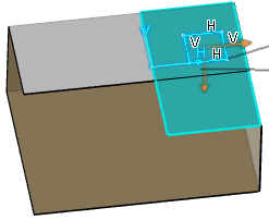
- In the Profile box, select the sketch.
It can contain one or more shapes, a wire, or a part.
A preview of the projected cutout appears. The vectors show
the side and the direction of the cutout.  -
Define the direction.
- Optional:
To choose between removing the material defined inside the profile (default behavior)
or surrounding the profile, click Reverse side
 . .
- Optional:
To invert the direction of the cutout pointed by the arrow, click Invert
direction
 . .
- To define the end and start limits, select the type and its associated parameters.
| Option | Description |
|---|
| Dimension | Creates the cutout using a depth value. |
|---|
| Up to next | Creates the cutout up to the next surface. |
|---|
| Up to last | Creates the cutout up to the last surface. |
|---|
- Optional:
To consider only the part of the profile that lies on the top or bottom surface, select
Lying on skin.
- Optional:
To thicken the profile, select Thick.
-
In Impact option, specify the type of faces impacted by the
cutout.
Note:
You can select the exact support in the box; for example, to avoid
confusions in the case of an overlapping:
-
To avoid overlapping issues on top or bottom faces, select Optimize
Geometry.
You can specify a gap between the input surface and the cutout result.
As impacts on both the top and bottom faces are taken into account, the result
of the cutout is improved.
|