Defining Kinematic Relationships

You can define kinematic relationships for non-command joints relative to the command joints with the Kinematic Relations command. Mechanism parameters such as link lengths, link offsets and user-defined variables may be defined.

For mechanisms (or robots) with closed loop chains, the number of Joints is greater than the number of degrees of freedom (DOFs). As a result, some joints are dependent on other joints (independent joints or DOFs) of the mechanism. In the current document, the dependent joints, independent joints (or DOFs) of the mechanism are referred as the non-command joints and command joints respectively.

The supported syntax for defining kinematics expressions for the non-command joints of the robot (or mechanism) are specified in the various dictionaries of the dialog as shown in the External View/Behavior section. A dictionary is a logical collection of the strings/characters for defining the kinematics expressions. For instance, the trigonometric functions like sin(x), cos(x), tan(x) are grouped under the Math dictionary. Similarly, the binary or unary operators like *, /, +, - etc are grouped under Operators dictionary and the pre-defined functions like SSSA, SASS etc are grouped under Functions dictionary.

Note: Kinematic relations are supported only in DELMIA (V+R) apps.

Kinematic relations are ignored:

  • in CATIA (3D) apps
  • when using mechanism assemblies
  • for sub-assemblies when a mechanism assembly is created using these sub-assemblies
This also applies to both inverse and user-defined forward kinematics.

This task shows you how to:


Before you begin: This command requires a mechanism with a fixed part, joints and commands. Please note that relations can only be defined on non-command joints (or engineering connections). These engineering connections must not be from flexible assemblies.

Defining Relations

This task describes how to define kinematic relations.

  1. Select Kinematic Relations
    You are prompted to select a robot.
  2. Select a robot.

    A dialog box listing the non-command joints of the mechanism appears.

  3. Select a joint from the list of non-command joints (or directly in the work area) for which a kinematic relation is to be defined, and click Add/Edit Relation button to define and compile the kinematic expression. If the selected joint already has a kinematic expression defined for it, this expression will be displayed in the expression editor. The existing expression may then be edited, if necessary.
  4. Joint expressions may be typed directly into the Define Joint Kinematic Relationship dialog without using the supplied dictionaries.
  5. Click OK to apply the defined relationship and close the dialog box.
  6. Dictionary types

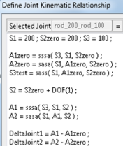
    The substrings used to compile a kinematic expression are categorized into various dictionaries as as shown in the Define Joint Kinematic Relationship dialog. Each dictionary contains a predefined set of strings.

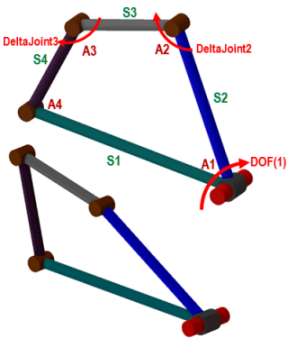
    The contents of the Degree of Freedom (DOF) dictionary is dependent upon the number of DOFs of the mechanism. For a mechanism with N degrees of freedom, the Degree of Freedom dictionary will have DOF(1), DOF(2), ...DOF(N).

    The User Variables dictionary will list all of the user-defined variables that have been created.

    OperatorsMathFunctions

    ;

    abs

    SASA

    ,

    acos, asin, atan

    SASS

    =

    acosr, asinr, atanr

    SSSA

    +

    cos, sin, tan

    RANGE

    -

    cosr,sinr, tanr

    INRANGE

    *

    exp

    SASASA

    /

    Int

    SASASS

    ^

    sqrt

    SASSSA1

    %

    floor, ceil

    SASSSA2

    (

    log,log10

    RAMP

    )

    The members of the Operators, Math, and Functions dictionaries are defined as follows:

    Operators
    ;Separator for expressions. Useful in case of multiple expressions for a non-command joint.
    , Arguments separator in a function
    = Assignment
    + Unary plus, binary addition
    - Unary minus, binary subtraction
    * Binary multiplication
    / Binary division
    ^ Exponent
    % Module operator
    ( Opening parenthesis
    ) Closing parenthesis
    Math
    abs(x)returns absolute value
    acos(x) asin(x) atan(x) returns arc cos, sin, tan in degrees
    acosr(x) asinr(x) atanr(x) returns arc cos, sin, tan in radians
    cos(x) sin(x) tan(x) Returns cos, sin, tan in degrees
    cosr(x) sinr(x) tanr(x) Returns cos, sin, tan in radians
    exp(x) Returns e raised to power x
    int(x) Returns integer value resulting from truncation
    sqrt(x) Returns square root
    floor(x) ceil(x) Returns floor, ceiling of x
    log(x) log10(x) Returns natural logarithm, logarithm base 10
    Functions Usage

    The following functions are useful for solving triangles given three sides of the triangle (s1, s2, s3) and one of its angle (a1). Note that all angles are in radians.

    sasa(s1,a1,s2) returns angle opposite side s1
    sass(s1,a1,s2) returns length of side opposite angle a1
    sssa(s1,s2,s3) returns angle opposite side s1

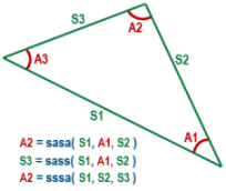
    The following functions are useful for solving convex quadrilaterals given four sides (s1, s2, s3, s4) and two of its angles (a1, a2). Note that all angles are in radians.

    sasasa(s1,a1,s2,a2,s3)returns angle between sides s3 and s4
    sasass(s1,a1,s2,a2,s3) returns length of unknown side s4
    sasssa1(s1,a1,s2,s3,s4) returns angle between sides s2 and s3
    sasssa2(s1,a1,s2,s3,s4) returns angle between sides s3 and s4

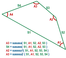
    A ramp function will assist in calculating the joint values of a joint whose upper and lower bounds are dependant on the values of another joint.

    yy = ramp(xx,x1,y1,x2,y2)returns yy as a linear function of xx, where the inputs x1, y1, x2, y2 are used to define the ramp.
    inrange(a,b,c) returns 1 if b <= a < c and 0 otherwise
    range(a,b,c) returns a if b < a, c if b > c and b otherwise
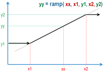
    Note:

    If xx is < x1 then yy stays at y1

    If xx is > x2 then yy stays at y2

    However, an expert user may directly key in the joint expression with out using the dictionaries provided. You may create/edit/delete user-variables (if required) using the button Create, Edit and Delete buttons. Any new variable created by you will be added to the User-defined Variables dictionary and subsequently can be used in the kinematic expression of the joints. The user variables thus defined are available for use in the kinematics expression of any NC joint of the mechanism. For a list of the values used in converting radians to degrees (or vice versa), plus the value of PI used in this software, click here.

Managing User Variables

This procedure decribes the management of user variables.

User Variables can be created, edited, and deleted using the Create, Edit, and Delete buttons in the User Variable section of the dialog box.

  1. Click Create to display the Create/Edit User Variable dialog box.
  2. Newly created variables are added to the User Variables dictionary and may subsequently be used in the kinematic expression of a joint. The following image shows that the variable defined above (MyVariable) has been added to the User Variables dictionary.

    When an item of the User Variable dictionary is selected, click Edit to display existing values in the editor.

    Notes

    • The definition of a kinematic relationship is only allowed for non-command joints. These joints must only be of Prismatic or Revolute type (e.g., a Cylindrical joint cannot have a kinematic relation).

    • Multiple expressions may be used to define the kinematics relationship for the non-command joints. Example:: For a non-command joint Revolute.4, the sequence of expressions could be L=10; UsrVar=sass(L, dof(1), L); sasa(L, UsrVar, L) Obviously, the evaluation of multiple expressions happens from left to right and the value of right most expression is set as the joint value (Revolute.4). In the above case, the result of sasa(L, UsrVar, L) is set as the joint value for the non-command joint Revolute.4.

    • User variables cannot have multiple expressions.

    • It is not mandatory to define kinematics relationship expressions for all the non-command joints. Any non-command joints without kinematics relationship will be ignored by the forward kinematics solver.

    • User-defined variable names in the kinematic relation may not have these special characters: tilde, exclamation mark, rate, hash, ampersand, underscore, question mark (~ ! @ # & _ ?).

    • Whenever the mechanism is simulated, if kinematics relationships are already defined for at least one of the non-command joints of the mechanism, then the forward kinematics solver for the mechanism will be based on the user-defined kinematics relationships rather than the DMU kinematics solver (currently in use).

    • If the expression has any syntax errors, you are prompted with the following error: Expression Input Error - The expression can not be evaluated to a single value. There is an operation, comma, or parenthesis missing.