You can import a DLL file to associate it with the machine in session and display
a list of services.
You can also create a virtual machine based on DLL files provided
by machine vendors.
Native Services or Virtual Machine Services
You can import a DLL file to associate it with the machine in session. You can
then display a list of services that you can add to or override the native
services of the application. You can choose between using native or virtual
machine services. The services available are as follows:
- Add or edit rules.
- Best orientation computation: Specify an orientation in which to print a
given part.
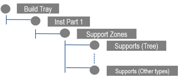
- Nesting computation: Position
the parts to print in the build envelope of the machine for a given set
of parts and number of instances required.
Note:
You can show the build envelope as a cube surrounding a machine
with Hide/Show Build Envelope
 in the Setup section of the action bar.
Use the Powder Bed Fabrication
App to specify the value of the build envelope in the
Rectangular Build Envelope section of
the Reference Parameters dialog box.
- Scan path generation: Compute
and order the scan path for a set of parts (and their supports) inside
the build volume of the machine.
- Post processor services:
Translate the geometry, slices, or scan path into a file that you can
send to the machine to start the print.
Before importing the DLL file, you must create a reference DLL file implementing
the following API:
int ComputeScanPathInAZone(const char* iParamsAsXML, const Object* iSlice,
	                    Object *& oScanPath)
A file containing the API is available in
<V6_install_dir>\startup\Additive\ExternalServices.h.
The table below lists the parameters to define in the reference DLL file:
| Parameter |
Description |
iParamsAsXML
|
Input parameter that corresponds to the
XML content. The content describes the parameters to use for
computation. |
iSlice
|
Input parameter that corresponds to the
C-structure. The structure contains the geometry of the zone
where to generate the scan path and other parameters.
|
oScanPath
|
Output parameter that corresponds to the
structure containing the generated path. |
Virtual Machine
You can create a virtual machine based on DLL files provided by machine vendors.
The services available are as follows:
- Best orientation computation: Specify an orientation in which to print a
given part.
- Nesting computation: Position the parts to print in the build envelope
of the machine for a given set of parts and number of instances
required.
- Scan path generation: Compute and order the scan path for a set of parts
(and their supports) inside the build volume of the machine.
- Post processor services: Translate the geometry, slices, or scan path
into a file that you can send to the machine to start the print.
You can also associate a configuration file to virtual machines. Click a
configuration file from the Configuration File list under
the Services
tab in the Reference Parameters dialog box. You can edit the
files available in the Configuration File list under .
Note:
Configuration files may be required to connect the virtual machine to a
third-party software.
Managing Machine Vendor Rules
When creating rules with the virtual machine, you can update the list of rules
declared on the machine using the associated machine vendor DLL files. Click
Update List of Rules under the
Rules
tab in the Reference Parameters dialog box.
Note:
Rules that come from machine vendor DLL files are considered external
rules. You cannot add or remove external rules defined on the virtual
machine. You can only browse and partially edit them. Some native services
may no longer be available when external rules are applied.
Scanning Optics Definition
You can define scanning optics to manage lasers during the printing simulation
process. You can give each parameter an associated Name
and ID, which appears in the Scanning
Optics dialog box.
Trajectories generated by the scan path computation are optimized based on each
laser's parameters and position. These new trajectories are stated in the output
files.
- Scanning Optics Parameters
- The following parameters are available:
| Parameter |
Description |
| Max Scan
Speed
|
Specifies the maximum scanning
speed. By default, the value is 10m/s. |
| Max Scan
Power
|
Specifies the maximum scanning
power. By default, the value is 600W. |
| Max Jump
Speed
|
Specifies the maximum jump speed.
By default, the value is 10m/s. |
- Beam Parameters
-
The following Beam parameters are available:
| Parameter |
Description |
| Focal
Diameter
|
Specifies the beam focal
diameter. By default, the value is 0.2mm. |
| Maximal Defocusing
Length
|
Specifies the maximum
defocusing length. By default, the value is 0.1mm.
|
- Scope Parameters
- Depending on the Shape Type selected (rectangle
or circle), the following parameters are available:
-
| Rectangle |
Circle |
|
| Parameter |
Description |
| Length
|
By default, the value is the
difference between the minimum and maximum Y
value. |
| Width
|
By default, the value is the
difference between the minimum and maximum X
value. |
|
| Parameter |
Description |
| Radius
|
By default, the value is:
150mm. |
|
- You can edit these parameters directly in the work area.
- Mirror Mounting Point Parameters
- You can also define the Mirror Mounting Point
using the X, Y, and Z coordinates. This is in the top center of the
build envelop by default.
Chamber
You can define chamber parameters to specify parameters for the additive
machine.
| Parameter |
Description |
| Gas Inlet Direction
|
Direction of the gas. By default, the value is
along the x-axis (value = 0). |
| Gas Inlet Distribution
Type
|
Distribution of the gas in the build chamber:
lateral or from center to border. |
| Gas Inlet Area |
Area of the entrance of the gas in the build
chamber. |
 to display a 3D
representation of the parameters available in the
to display a 3D
representation of the parameters available in the 
 command
from the
command
from the