Manual Support Creation
When Create Manual Supports is selected, the Manual
Support Creation dialog box appears. You can use this dialog box to
create defined supports in specific support zones, compute support zones, and view a
quick preview of computed support zones.
You can manually define support zones by defining the Zone and
Support parameters.
Support Structure Propagation
You can propagate the current part to a product support structure on positioned part,
using Propagate Structure.
The Propagate On dialog box displays all the valid, eligible
instances for support propagation.
This option is only displayed if:
- The positioned part has calculated support structures.
- There is more than one occurrence of the positioned part that originates
from a singular part to produce.
It is only possible to propagate support structures if the two positioned parts are
defined along the same X-Y plane and have the same rotation along the Z-axis.
Copy Support Properties
You can copy the shape of the current support to a selection of other supports.
This command can be accessed by:
- Clicking Copy Properties
 from
the context toolbar that appears when you select a support structure in the work area. from
the context toolbar that appears when you select a support structure in the work area.
- Clicking Copy Supports to other instances from the
support context menu in the manufacturing view.
Only supports with an identical structure (surface, edge, or point) can be selected
for duplication.
Support Structure Assessment
You can specify various support parameters using the Support Structure
Assessment dialog box.
Open the Support Structure Assessment dialog box by doing one of
the following:
- Click Quick Support Analysis
 from the context toolbar in the work area when establishing the build layout. from the context toolbar in the work area when establishing the build layout.
- Click Analysis
 from the Generate Support
Structure dialog box. from the Generate Support
Structure dialog box.
You can use the Support Structure Assessment dialog box to:
- Edit the minimum surface angle for the set of facets needing supports.
- Edit the maximum surface angle for the set of facets needing supports.
- Edit the orientation of the part using the Robot while the command is active. This command dynamically evaluates the
surface area for the modified orientation.
Based on the color chosen for the minimum/maximum surface angle, color legend updates
itself, and the color changes gets reflected on the facets of the overhanging parts.
The following parameters can be modified:
| Parameter |
Description |
| Minimum surface angle
|
Specifies the minimum surface angle allowed on
the part. |
| Maximum surface angle
|
Specifies the maximum surface angle allowed on
the part. |
| Transparency
|
Specifies the transparency of the color
visualization. |
| Supported Zones Area
|
Indicates the computed surface area of the
support zone. This measurement is given in square meters.
|
| Supported Edge Length
|
Indicates the computed surface area of the
edge length. This measurement is given in square millimeters.
|
| Number of Supported
Points
|
Indicates the number of supported points.
|
| Occlusion WRT
Front-face
|
True: Displays only the previewed
zones visible in the current view.
False: Displays all previewed zones.
|
Wire Support Edition
You can select, edit, and delete wire support structures in the work area.
Use the commands in the context toolbar to edit or delete a selected support structure face.
You can also use the Scaling
 command to display a Robot that allows you to scale supports on the bottom or an intermediate level. command to display a Robot that allows you to scale supports on the bottom or an intermediate level.
Note:
This command is only available with wire support structures.
Wire Angled Support Creation
You can create an angled wired support structure.
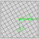
Select a wired support in the work area, then select Edit Supports
 from the context toolbar. Manipulation points appear in the work area if it is possible to create an angled support structure. Points that appear in
red cannot be manipulated, whereas points that appear in green are open to
manipulation. from the context toolbar. Manipulation points appear in the work area if it is possible to create an angled support structure. Points that appear in
red cannot be manipulated, whereas points that appear in green are open to
manipulation.
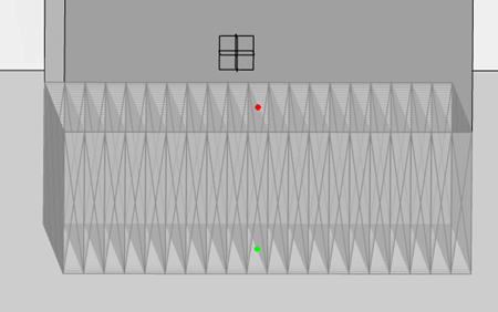
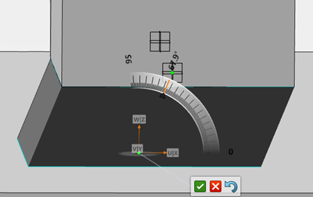
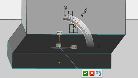
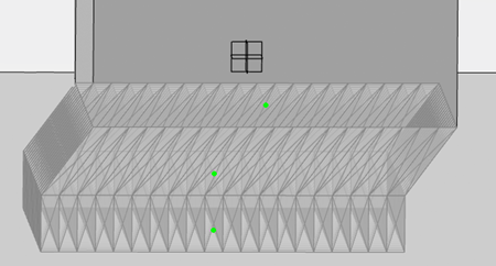
Clicking a green manipulation point displays a Robot that you can use to define the various angles of the angled support. Moving the
Robot dynamically recomputes the support structure.
Along the X-axis:
Along the X and Y-axis:
When you are finished, use the context toolbar to validate, reject, or revert your changes.
Rules for Generating Supports
You can generate supports by creating rules that apply to the whole part or to
specific zones of the part only.
Assign or edit a support rule using:
- Create or Edit Rules
 command in the
Generate Support Structure dialog box. command in the
Generate Support Structure dialog box.
- Rules Management
 command in the
Setup section of the action bar. command in the
Setup section of the action bar.
Note:
Before creating support structure rules, you must define zones on the part where
supports need to be specified, and choose a shape for the supports.
Zones
Lets you define an area on the part where to generate supports.
A zone corresponds to an area defined between a minimum angle value and a maximum
angle value. You can generate supports on:
Depending on the zone selected, the following parameters are available:
- Surface

-
| Parameter |
Description |
| Minimum Surface
Angle
|
Minimum angle between the part
surface and build tray surface. The value must be
less than 90°. |
| Maximum Surface
Angle
|
Maximum angle between the part
surface and build tray surface. The value must be
greater than or equal to 0. |
| Minimal Surface
Width
|
Precision of the zone
computation. |
| Tolerance
|
Specifies the maximum
deviation allowed between the design part and the
manufactured part. |
| Ground
Type
|
Lets you decide if the roots
of the support structure stand on the build tray,
on the part or on both. |
- Edge

-
| Parameter |
Description |
| Minimum Edge
Angle
|
Minimum angle between the part
edge and build tray surface. The value must be
less than 90°. |
| Maximum Edge
Angle
|
Maximum angle between the part
edge and build tray surface. The value must be
greater than or equal to 0. |
| Computation |
Lets you specify the support's computation
method:
Can be either:
- All: follows the sharp
edges
- Lowest line: detects the
lowest line on the part.
|
| Minimum
Length |
Minimum length of the lowest
line. Note:
Only available if
Computation is set to
Lowest line.
|
| Exclude Edge
Already Supported
|
Ignores the part edges at an
angle that equals the maximum angle value with
respect to the build tray. |
| Maximum Angle for
Zones Already Supported
|
Maximum angle allowed between
the part surface and build tray. This value is
used for the Exclude edges included in
surfaces supported parameter. |
| Ground
Type
|
Lets you decide if the roots
of the support structure stand on the build tray,
on the part or on both. |
- Point

-
| Parameter |
Description |
| Exclude Points
Included in Surfaces and Edges
Supported
|
When selected, ignores the
points of the part at an angle that equals the
maximum angle value with respect to the build
tray. |
| Maximum Angle for
Zones Already Supported
|
Maximum angle allowed between
the part surface and build tray. |
| Ground
Type
|
Lets you decide if the roots
of the support structure stand on the build tray,
on the part or on both. |
Shapes
The following shapes are available for supports:
-
 Wire Wire
-
 Conical Conical
-
 Tree Tree
-
 Volume Volume
- None
| Wire |
Conical |
Tree |
Volume |
|
Depending on the type of zone selected
(Surface,
Edge, or
Point), the following
parameters are available:
| Parameter |
Description |
| Pattern
Type
|
Lets you choose between an
offset or grid pattern. |
| Spacing
|
Specifies the density of the
pattern. |
| Radial
Offset
|
Specifies the offset
spacing. |
| Direction
angle
|
Specifies the direction of
the grid support structure. See Additional Wire Support Parameters. |
| Z Offset to
Top |
Creates a void between the
support structure boundary and the top
zone. |
| Z Offset to
Bottom |
Creates a void between the
support structure boundary and the bottom
zone. |
| Rib
width
|
Specifies the width of the
transverse reinforcement. |
| With
envelope
|
Creates an additional wire
that follows the peripheral loop of the surface
zone. |
| Fragmentation
|
See Additional Wire Support Parameters. |
| Fillet |
Adds fillet perforations on
the support. |
|
| Parameter |
Description |
| Cone
Radius
|
Specifies the radius of all
the nodes in direct contact with the part.
|
| Space Between
Cones
|
Specifies the distance
between cones to control the density of the
supports. |
| Radial
Offset
|
Specifies the offset
spacing. |
| Z Offset to
Top |
Creates a void between the
support structure boundary and the top
zone. |
| Z Offset to
Bottom |
Creates a void between the
support structure boundary and the bottom
zone. |
| Fillet |
Adds fillet perforations on
the support. |
|
| Parameter |
Description |
| Leaf
Radius
|
Specifies the radius of all
the nodes in direct contact with the part.
|
| Radius Increase
Rate
|
Specifies the rate at which
the tree thickens from the leaves to the root of
the tree. |
| Branch Internal
Thickness
|
Specifies the skin thickness
for hollow branches. If the value equals zero, the
branches are considered solid. |
| Maximum
Angle
|
Specifies the maximum angle
allowed for branches with respect to the building
direction. |
| Space Between
Leaves
|
Specifies the spacing
between leaves to control the density of the tree.
|
| Radial
Offset
|
Specifies the offset
spacing. |
| Z Offset to
Top |
Creates a void between the
support structure boundary and the top
zone. |
| Z Offset to
Bottom |
Creates a void between the
support structure boundary and the bottom
zone. |
| Fillet |
Adds fillet perforations on
the support. |
|
| Parameter |
Description |
| Motif
|
Customizes the solid
structure by letting you select any polyhedral
motif you have created. |
| Scale
|
Specifies the scaling factor
applied to the motif before replication, to
control the density of the lattice structure.
|
| Skin
Thickness
|
Creates a solid skin around
the lattice structure when you specify a value.
|
| Z Offset to
Top |
Creates a void between the
support structure boundary and the top
zone. |
| Z Offset to
Bottom |
Creates a void between the
support structure boundary and the bottom
zone. |
| Fillet |
Adds fillet perforations on
the support. |
Note:
Negative values are accepted for Offset on Volume
supports. With negative values, the support
structure penetrates the part, but not the build
tray.
|
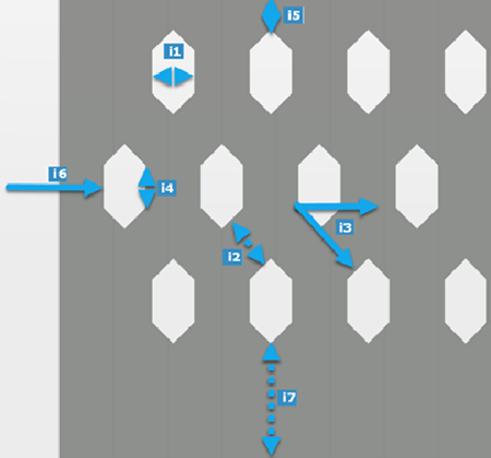
Fillet
- Fillet on Wire
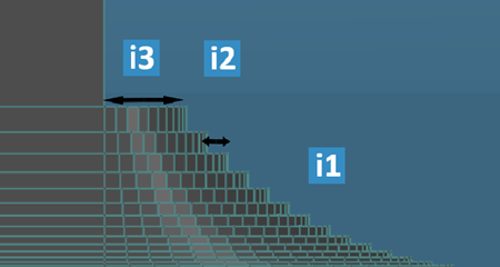 -
| Legend |
Parameter |
Definition |
| i1 |
Fillet
Radius
|
Specifies the perforation
radius |
| i2 |
Fillet Wired
Spacing
|
Specifies the perforation
spacing. |
| i3 |
Fillet Wired
Offset
|
Specifies the perforation
offset. |
- For the Perforation parameters, see Perforation.
- Fillet on Conical, Tree, and Volumic Shapes
-
- Fillet on Conical and Tree
Shapes
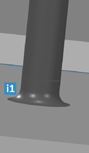
| Legend |
Parameter |
Definition |
| i1 |
Fillet
Radius
|
Specifies the perforation
radius |
- Fillet on Volumic Shape
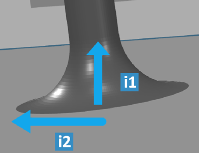
| Legend |
Parameter |
Definition |
| i1 |
Fillet
Height |
Specifies the perforation
height |
| i2 |
Fillet
Radius
|
Specifies the perforation
radius |
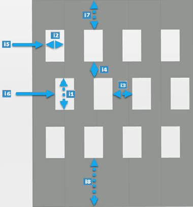
- The perforations are defined by their shape, their spacing pattern, and their depth.
- Perforation Shape
-
- Cylindrical
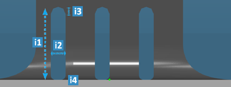
| Legend |
Parameter |
Definition |
| i1 |
Height
|
Specifies the perforation
height |
| i2 |
Width |
Specifies the perforation
width |
| i3 |
Top
Radius
|
Specifies the perforation
top radius |
| i4 |
Bottom
Radius
|
Specifies the perforation
bottom radius |
- Ovoid
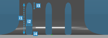
| Legend |
Parameter |
Definition |
| i1 |
Height
|
Specifies the perforation
height |
| i2 |
Width |
Specifies the perforation
width |
| i3 |
Top
Height
|
Specifies the perforation
top height |
| i4 |
Bottom
Radius
|
Specifies the perforation
bottom radius |
- Triangular
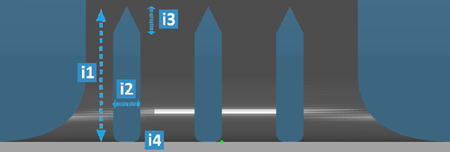
| Legend |
Parameter |
Definition |
| i1 |
Height
|
Specifies the perforation
height |
| i2 |
Width |
Specifies the perforation
width |
| i3 |
Top
Height
|
Specifies the perforation
top height |
| i4 |
Bottom
Radius
|
Specifies the perforation
bottom radius |
- Spacing Pattern Type
-
- Curvilinear
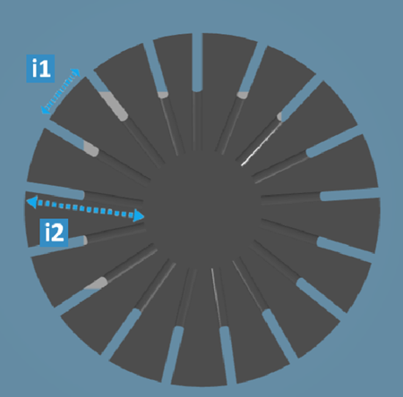
| Legend |
Parameter |
Definition |
| i1 |
Step
|
Specifies the spacing between the perforation along the
curve |
| i2 |
Lenght |
Specifies the perforation depth |
- Mono-directional
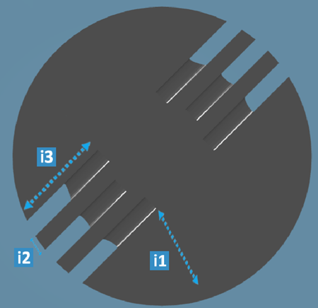
Note:
The perforations are
perpendicular to a reference direction (by default
X Ref Axis).
| Legend |
Parameter |
Definition |
| i1 |
Additional Angle
to X Ref axis |
Specifies the angle between X Ref axis and the reference
direction |
| i2 |
Step
|
Specifies the spacing between the perforations along the reference
direction |
| i3 |
Lenght |
Specifies the perforation depth Note:
Unavailable if
Depth Type is set as
Up to
next.
|
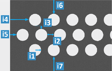
- XY Grid
Note:
The perforations are
perpendicular to a reference direction (by default
X Ref Axis) and along the reference
direction.
| Legend |
Parameter |
Definition |
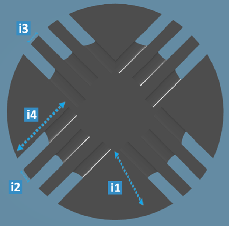
| i1 |
Additional Angle
to X Ref axis |
Specifies the angle between X Ref axis and the reference
direction |
| i2 |
X
Step
|
Specifies the spacing between the perforations along the reference
direction |
| i3 |
Y
Step |
Specifies the spacing between the perforations along the direction
perpendicular to the reference direction.
|
| i4 |
Lenght |
Specifies the perforation depth Note:
Unavailable if
Depth Type is set as
Up to next.
|
- Depth
-
| Type |
Description |
| Fixed
|
The perforation depth is
limited by a fixed value. |
| Up to
next |
The perforation goes through
the support. Note:
If Spacing pattern
type is defined as
Curvilinear, this is
unavailable.
|
Rules for Generating Anchors
It is possible to define anchors between the supports and part. Anchors are
thinner than supports, allowing you to remove the support structure from the
manufactured part.
Anchors have a shape similar to the one below:

When using anchors, the part is automatically subdivided into geometric shapes. One
geometry shape corresponds to one anchor. It is possible to customize the geometry
shape associated with one anchor by modifying the value of the Grid
length or Space between anchor points
parameters.
To define anchors, select the With anchors check box in the
dialog box that appears when you select a shape for a support. The following
parameters are available:
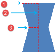
The following
parameters are available:
|
 Surfaces
 Edges
Edges  Points of a part
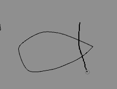
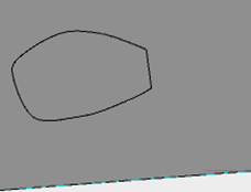
  allows you to draw the required support
zone directly on the part in the work area. Note: Free Form
 is only compatible with the Surface and
Edge zone types.
  allows you to define a sectioning plane
in the work area. Use the Robot to position the plane. Clicking Sectioning
 again hide the plane and the part
becomes fully visible again.
 from the


 command in the





 in the image above.
 in the image above.
  in the image above.