Creating Seam Search Trajectories | |||||
|
| ||||
-
From the Arc section of the action bar, click Create Seam Search Trajectory
 .
You are prompted to select a robot.
.
You are prompted to select a robot. - Select the an edge or surface of the weld gun to be used for constraining the position.

Edge: is populated with the selected geometry.
Note: If you make a different selection, the previous selection will be replaced by the new one. If the you select a geometric element from a different weld gun, the respective fields update to the new device and the element will become the selection. -
Select a surface.
A touch point is created on the surface and the orientation Robot is snapped to it.
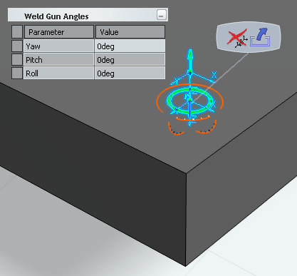
The Weld Gun Angles immersive panel is displayed, and allows you to set the orientation of the weld gun with respect to its target surface by entering precise values for Yaw, Pitch and Roll directly in the panel. Any changes made to the orientation using the orientation Robot are also immediately reflected in this panel.
Note: The Weld Gun Angles panel is not displayed when a via point is displayed instead of a touch point.The touch point search path is added to the Search Path list in the Parameters
 section of the dialog box.
- Each touch point is identifiable by its Search Path, which includes the via points leading up to the touch point and ends with the touch point itself. The complete seam search trajectory is composed of the search paths in the given sequence in the list.
- The number of points for a given touch point is displayed in the Points column. There are always at least two points (one via point and one touch point). There is no upper limit on the number of points that can be defined.
The appearance of the line (Line Type, Color and Thickness) is defined under Line Properties of the General tab.
-
Select another surface.
The touch point is created on the surface and added to the Search Path list.

- Select another surface.
The touch point is created on the surface and added to the Search Path list.
 Note: You can undo and redo selections via and , respectively.
-
Select OK to create and save the seam search trajectory.
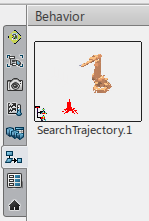
The new trajectory appears in the Behavior side tab of the immersive browser: