Create a trajectory
You can create an arc trajectory.
-
From the Arc section of the action bar, click Create/Edit Arc Trajectory
 .
.
The Create Arc Trajectory dialog box appears.
- To select a different weld gun, click within the Tool field.
The Select Weld Gun dialog box appears.
When a tool is selected, it is highlighted in 3D and its TCP is indicated by an orientation Robot. If a different tool is selected or the TCP is changed, the highlight and orientation Robot are updated after the selection. If the selected tool is the default tool for a robot in this station, the Robot field displays the name of the robot.
- Select Track target with attached robot to have the robot and gun follow the selected tag.Note: The Tags and Tool options in Preview section of the Create Arc Trajectory dialog box must also be selected to see the tool track the target.
Tracking the target requires that the following conditions are satisfied:
- The selected tool is attached to a robot (identified by the Robot field).
- Tools and Tags are both selected.
- There are no reachability issues between the robot and the tag. If a tag is not reachable, the position and orientation of the selected tag must be changed, as the robot can not be jogged manually while the command is active.
- Select Display in the Output list to view a transient visual display of the current tool at each weld point.
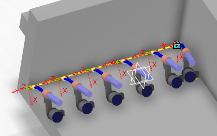 Note: This feature is supported for trajectories that do not exceed 100 tags.
You can alternatively select Resource in the Output list to create a new tool instance for each point in the trajectory that is aggregated to a new manufacturing cell resource. The new manufacturing cell is inserted under the manufacturing cell of the tool's parent.
- Select OK to close the Select Tool dialog box.The Create Arc Trajectory appears.
-
From the list, select the method by which the trajectory will be created.
-
Select
 to begin selecting the entities that will define the trajectory.
For Tags, the Select Tags dialog box is displayed.
For Curves, the Select Curves dialog box is displayed.
For Surfaces Intersection, the Select Surfaces dialog box is displayed.
For Parts Intersection, the Select Parts dialog box is displayed.
For Bead Fastener, the Select Bead Fastener dialog box is displayed.
-
Select the entities that will define the trajectory.
-
Select OK in the dialog box.
A contour is added to Create Arc Trajectory.
Note: When Parts Intersection is used, a list of contours is added to Create Arc Trajectory.A contour based on your selections is shown in the work area.
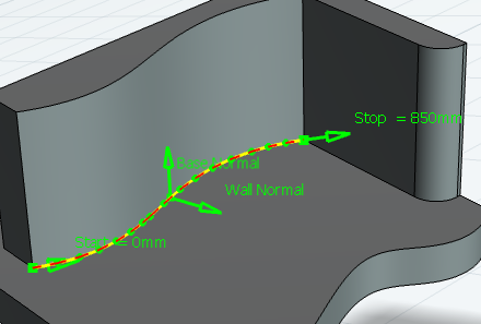
You can use the Preview options to hide or display the tags, tool and clash.
You can repeat steps 2 through 5 to add multiple contours as necessary.
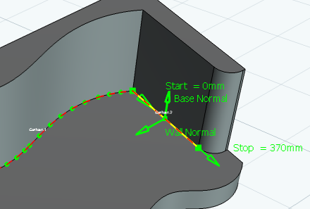
Each contour is added to the list in Create Arc Trajectory.
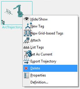
You can delete a contour by highlighting it and selecting
 , as well as move a highlighted contour up or down in the list with
  and
and  .
. -
Select the Sampling
 tab.
tab.
The Sampling options are displayed.
The work area displays a graphic representation of each of these parameters.

-
Select the Mode to use.
The contour in the work area is updated in real-time as the Tag Creation options are set.
-
Select the Offset
 tab.
tab.The Offset options are displayed.
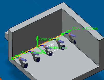
- Set any offsets from the beginning and end of the trajectory, as well as any offset distances from the base and wall if necessary. The contour is updated in the work area as the distances are entered.
-
Select the Orientation
 tab.
tab.
The Orientation options are displayed, allowing you to define the Base Axis. You can select from four options: Roll, Base, Rake and Constant, where Constant allows you to define a global base axis that is independent of the trajectory, and its orientation is same as that of the manufacturing cell that aggregates the product.
- Select the Tags
 tab.
tab.A list of all of the current tags is displayed in a table that indicates Type, Base, Rake, Roll, and Nominal Base for each tag. It also provides a means of selecting specific tags when multiple tags are very close to each other in the work area
-
Select the Approach/Depart
 tab.
tab.The Approach/Depart options are displayed.
- Select Approach and Depart to include them in the trajectory.
The Approach and Depart paths appear in the trajectory. The Distance values for each can be modified in 3D by dragging their respective end-points, or directly specified in the dialog box.
-
Select the Flare points
 tab.
tab.The Flare points options are displayed.
- Select Flare Start and Flare End to include them in the trajectory.
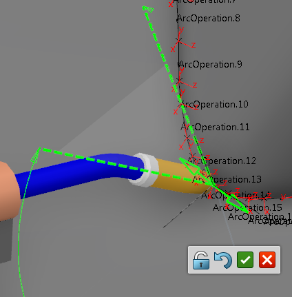
The Flare Start Angle and Flare End Angle appear in the trajectory. You can drag these angles in 3D to set their radius value, or define these values directly in the dialog box.
You can also edit the Distance and Angle values for each of these parameters in the dialog box and the work area updates in real time.
- Select OK to create the arc trajectory.
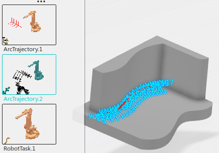
The new trajectory is added to the model. 