Open the System Editor
When you start your app, the
System Editor appears in the main frame. It is easily identified by its characteristic
grid.
When you leave your app,
the System Editor is replaced with the default editor of the target application.
Create Systems and Operations in the System Editor
When you open the System Editor, a PPR Context object and a root System are created.
You can then create systems and operations on the System Editor grid. One way of
doing this is by using the System/Operation Authoring
context toolbar that appears when you double-click in the editor.
If Fastener Planning is started by changing from another application, then no PPR
Context object is created and the existing context is used. If there are already
Systems below this PPR Context, no new Systems are created and System Editor
displays the existing root System.
-
To create a new system or
operation, double-click the grid.
The new System tile must be at least one tile away from any other tile. A context toolbar appears for inserting new or existing systems and operations on the
grid. For details, see System/Operation Authoring Context Toolbar.
-
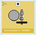
Click
Insert a General System
 in the
Systems Authoring
context toolbar. in the
Systems Authoring
context toolbar.
A new system tile is created on the grid. 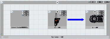
-
In a similar way, create operations on the grid using the
Operation Authoring
context toolbar.
Edit System or Operation Properties
You can edit the reference, instance, configuration, and
effectivity attributes of a system or an operation in the
Properties dialog box.
-
Right-click a system or an operation in the System Editor and
select
Properties.
The
Properties dialog box appears. The
attributes are organized in tabs as follows:
- Reference
- Instance
- Effectivity
- Configuration
-
Make the required modifications to the attributes and click
OK.
Access Properties of Implemented Objects
You can access the properties of implemented objects (such as
products or fasteners) of a system in the
Properties dialog box.
-
Right-click the required System tile or tree node and select
Implemented Object Properties.
The
Properties dialog box appears.
-
In the
Current selection list, select an
implemented object of the selected system (a product, for example).
The properties of the implemented object appear.
Delete a System or Operation
You can delete a system or an operation using the
Delete contextual command.
-
Right-click the system or operation that you require to delete.
-
Click
Delete.
The
Edit Links & Relations Options dialog box
appears. It proposes options for handling broken links.
-
Select an option as follows:
-
Automatic: automatically reconnects broken
links whenever it is possible to do so. Otherwise a warning is displayed. This
is the recommended option.
-
Browse: displays the
Edit Links & Relations dialog box,
which you can use for manually reconnecting any broken links. For more
information, refer to
3DEXPERIENCE
Native Apps:
Links and Relations.
- No analysis: the links are not
analyzed and any broken links are not reconnected.
-
Click
OK to delete the system or operation.
Note:
If required, you can click
Undo
 to recover the system or operation. to recover the system or operation.
Reframe the System Editor on a Tile
When you use the
Reframe On contextual command on a system or
operation tile or tree node, the editor zooms and centers on the tile.
-
In the tree,
right-click the system or operation that you want to reframe.
-
Click
Reframe On.
The editor zooms and centers on the corresponding tile.
Note:
You can run
Reframe On on an operation in the tree when
the operation's system tile is visible on the grid. In this case, the system
tile expands and the
Reframe is done on the operation tile.
Center Tree to Locate a System or Operation
When you use the
Center Tree contextual command on a system or
operation tile, the tree expands and positions the corresponding tree node in
the middle of the work area.
-
Right-click a system
or operation tile.
-
Click
Center Tree.
The tree is expanded and the corresponding tree node is
positioned in the middle of the work area.
Use Visualization Modes
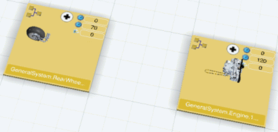
You can manage the display of the 3D representation on system
and operation tiles using a number of visualization modes.
Use Visualization Modes on System Tiles
You can manage the display of the 3D representation on a
system tile using visualization modes. The 3D view on the tile is the result of
the items realized on the system.
-
From the
App Options
panel, click
Show All Parts
 . .

All parts are visible on the system tiles.
-
Click
Show Only Concerned Parts
 . .
Only the parts concerned are visible on the system tiles.
-
Click
Show Unconcerned Parts as Transparent
 . .
Only the parts concerned are visible on the system tiles and
the other parts are transparent.
-
Click
Hide All Parts
 . .
Parts are no longer displayed on the system tiles. This is
particularly useful for improving performance when large 3D representations are
used.
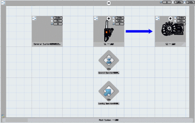
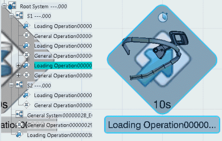
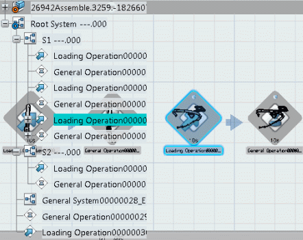
Use Visualization Modes on Operation Tiles
You can manage the display of the 3D representation on an
operation tile using the visualization modes. The representation is determined
by the items implemented by the operation and the visualization
mode. This may be a 3D representation of the implemented item or a
2D icon representing the item type.
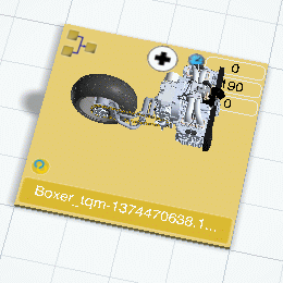
The following scenario illustrates the case where an
Unloading operation implements a Provided Part.
-
Add an Unloading operation that implements the Provided Part
of the Air Filter part shown below.
-
From the
App Options
panel, click
Show All Parts
.

All parts are visible on the operation tiles. The Air Filter
is not shown on the Unloading operation tile because it is no longer part of
the resulting output of this operation.
-
Click
Show Only Concerned Parts
.

Only the concerned parts are visible on the operation tiles.
The Air Filter is shown because the concerned part of the Unloading operation
is the Air Filter.
-
Click
Show Unconcerned Parts as Transparent
.

Only the concerned parts are visible on the operation tiles
and the other parts are transparent.
The Air Filter is shown on the Unloading operation tile
because it is concerned by that operation. All the other parts from previous
operations are transparent.
-
Click
Hide All Parts
.

Parts are no longer displayed on the operation tiles. If
operations implement items, the 2D icon images of the implemented
items are displayed on the tiles. This is particularly useful for
improving performance when large 3D representations are used.
-
Optional: Collapse the operations to visualize on
the father System tile.
Because the Air Filter is not part of the output of
this system, the system tile displays the following result as output:
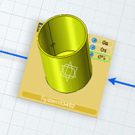
Use Scale Modes
You can manage the scale of the 3D representation on the System
tile using a number of visualization modes.
-
Load your 3D representation in the System Editor.
-
Expand the root system.
-
From the
App Options
panel, click
Display Parts in Absolute Scale
 . .
The 3D representations displayed above each tile are
displayed in an absolute way: they take up the same percentage of space above
the tile.

-
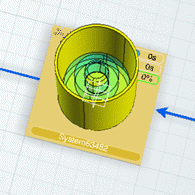
Click
Display Parts in Relative Scale
 . .
The 3D representations are displayed within the context
of the highest scoped item. This lets you see the relative size
and positioning of each 3D representation.
The 3D representations are displayed according to
the
Scale factor for 3D
representation above the tile specified in
.
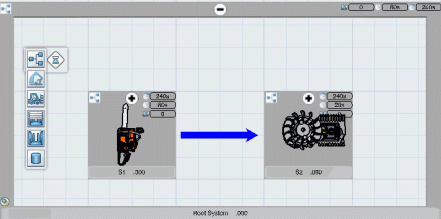
Item to System Assignments Using the Item
Editor
You can drag items from the Item
Editor to assign them to systems in the System Editor. By doing this, you can
create operations on target systems.
-
In the Item Editor, under the root Manufacturing
Assembly create a Manufacturing Assembly with several Provided Parts.
-
Switch to the System Editor, and create two systems.
-
Create a scope between and root System.
-
Switch back to the Item Editor.
-
Position the Item Editor and the System Editor in
the top and bottom frames of the window.
-
Drag the Manufacturing Assembly tile from the Item
Editor to the first System tile in the System Editor.
The Manufacturing Assembly is assigned to the system.
Several operations are created.
-
Drag a part from the Item Editor to the second
System tile in the System Editor.
The corresponding Provided Part is now assigned to the
system. A Loading operation is created.
Use the F5 Key to List Objects Assigned to Systems and
Operations
By pressing the F5 key, you can list the objects that are
assigned to systems and operations. For each system, the assigned parts, items,
operations, and fasteners are listed. For each operation, the assigned parts and items
are listed. You can
customize the displayed attributes with the Customize F5 List with Attributes
business logic.
-
Press
F5 on the keyboard to display assigned
objects in an F5 list.
The
Parts tab is selected by default. Clicking
any part in the list highlights the corresponding part in the 3D representation
on the tile.

-
Select the
Man. Items tab to list the items implemented in the system or the items implemented by the
operation.
Note:
The Item Editor has a similar F5 list. You can
drag an item from the F5 list of the Item Editor to
the System Editor.
-
Select the
Operations tab to list the operations
contained in the system.
Clicking any operation in the list highlights the
corresponding part in the 3D representation on the tile.
You can use the Process Gantt for displaying the
operations owned or executed by a system.
Show Information for Selected System and Operation
Tiles
You can use the
Show Information contextual command to display
information panels for selected system and operation tiles.
-
Select one or more System or Operation tiles, then right-click
and select
Show Information.
An information panel appears next to each selected tile.
- Optional:
Press the
F4 key to hide the information panels.
You can show the panels again by pressing the
F4 key again.
Note:
By default, the description of the system or operation is given in the information panel.
Business logics are available to let you customize the information to be
shown in the panel: By default, DELPPRCustomizedLabelInformation_ID returns a single
attribute name Description and
DELPPRGetValueCustomizedInformation_ID returns the corresponding
V_description attribute value of the system or
operation instance.
|