General Information
Whenever a stiffener/beam welds to a plate, the plate undergoes deformation because
the heating-cooling effect encountered by this.
- Material shrinkage: This depicts how the material (shrinkage) compensates industrially.
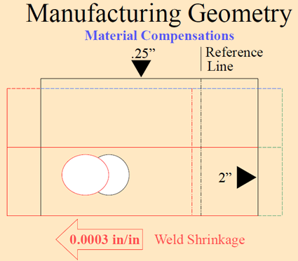
There is an additional material provided on both sides of plate edges, and also an
offset on the reference line feature to compensate the shrinkage. When the plate shrinks
after welding the plate with additional material, it reaches its design specification
indicated with a black rectangle. The reference line reaches its correct position,
example, from red to black as in the above figure. To summarize, shrinkage is
compensated by providing additional material at the ends, and a cumulative offset to all
marking features at the beginning itself. Although the shrinkage compensation applies to
manufacturing features, the philosophy integrates into this app from process planning
onwards by having a different process model for shrinkage. So, addressing shrinkage
compensation requirements involves three steps:
- A new process data model for shrinkage.
- A new IPM/MA data model for shrinkage.
- The geometrical modifications
requires at the manufacturing feature layer.
- Material distortion: addressed in subsequent releases.
Shrinkage uses dimensional compensation on manufacturing features be an added margin on
both ends of the plate or an offset applied to the marking line manufacturing feature.
However, we also need the real representation of manufacturing features, example, to be able
visualize under MAs. Then this situation demands two different IPMs:
- One with shrinkage compensated manufacturing features, namely
IPM_SC, where in each most of the manufacturing features
(especially the marking line) are geometrically modified to account for shrinkage.
- Other that consists of manufacturing features with correct representations so that they
visualize at MA level. This is nothing but the IPMs that we have now in this app.
The picture above depicts both these IPMs with one overlapping on the other to indicate the
dimensional compensations. So, it is evident that we need two IPMs for one design piece part
to address the shrinkage compensation.
To seamlessly integrate this two IPMs for one design approach into the process model, it is
essential that there is altogether a different process data model. This model captures the
shrinkage at the assemble process level. To address shrinkage for flat panel and curved
panels independently, ensure that there are no loose ends in the model.
Flat Panel with Shrinkage
This section explains the Item structure for a flat panel with a
shrinkage.
Item Structure for a flat panel with shrinkage part.
Functional Item Data Model - Basic planning for flat panel with shrinkage.

We observe:
- A Shrinkage (An item, which is of type Transform) is created for
each plate under the manufacturing assembly as a sibling to the plate’s manufactured
part.
- Shrinkage (Item) creates as child to manufacturing assembly because the shrinkage
happens only during welding that captures under manufacturing assembly.
- DR link creates between Shrinkage (Item) and Manufactured part.
- Shrinkage has DM link to real IPM that gets instantiated under MA, whereas manufactured
part has DM link to SC_IPM, a new IPM that contains manufacturing features with
shrinkage compensation.
- SC_IPM is instantiated under IPM.
- All such IPMs are prefixed by SC_.
- Shrinkage occurs at the time assemble, example, welding the profiles to plates. However,
the compensation accounts even before we mark and cut the plate. So, it is obvious that
SC_IPM is in the in-process models until proceeding with
assemble, and IPM is in the in-process model from there on.
Hence,
- Manufactured part has DM link to SC_IPM and shrinkage (Item)
has DM link to IPM.
- SC_IPM instantiates under IPMs.
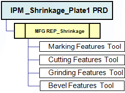
- SC_IPM have a Mfg REP that consists of all the manufacturing
tools and features like IPM, but there is no design instance under
this.
Curved Panel with Shrinkage - Curved and Flattened
This section contains information for a curved panel with shrinkage.
It is complicating for curved panels, as they already have two IPMs, curved and flattened.
Curved Panel
Extending the same approach (but with a minor change) to curved panels also, with
shrinkage, has three IPMs for one design piece part. This is confusing sometimes, as
welding done on the curved plate, and hence there can be a curved IPM that compensates for
shrinkage. But, to produce curved SC_IPM start from flattened IPM
and hence it is inevitable to have flattened IPM that is compensated for shrinkage.
However, in such cases, Flattened_IPM does not need shrinkage and
hence there is only one flattened IPM that is called Flattened_IPM
but with shrinkage compensated. As there is only one flattened IPM.
Functional Item Data Model - Basic planning for curved panel with shrinkage.

This shows the item data model for the curved panel with shrinkage and basic planning. In
the curved panel case, there are few extra points in addition to all the points discussed
on the flat panel case.
- Forming has DM link to SC_IPM whereas all other child items of manufactured
part have a DM link to Flattened IPM.
- Shrinkage (Item) has DM link to curved IPM, which is instantiated under
MA.
Flattened IPMs
For curved IPMs, the same logic as of the flat plate scenario applies, but for flattened
IPMs there are subtle changes:
- Manufactured and Formed has DM link to SC_IPM (Curved) and Shrinkage (Item) has
DM link to IPM (Curved).
- Flattened IPMs are the IPMs that indicate how a plate is marked
and cut from stock so that it reaches IPM curved, at forming.
However, in the case of shrinkage, these flattened IPMs not only indicate the flattened
representation of curved IPM but also account for shrinkage compensation. Then these
represent SC_IPM, when forming. In the case of shrinkage,
flattened IPMs is inclusive of shrinkage compensation. Represents separate flattened IPM
without shrinkage.
- Fabricate (in basic type), and all detailed items (in detailed type) has a DM link to
the flattened IPMs.
In the case of shrinkage curved panels, the methodology to compute flattened IPM varies
slightly in comparison to curved panels without shrinkage. In the case of later, flattened
IPM is created by flattening the curved IPM surface and after transferring the all curved
manufacturing features to the flattened surface. But for the former case, there is an
additional step introduced. First compensate for shrinkage on curved IPM, and then process
that curved IPM for flattening and flattening IPM creation. Then has shrinkage compensated
directly. Flattened IPM is created by flattening IPM_SC in the
former case, whereas they are created by flattening IPMs in the
latter case.
Dimensional/Geometrical Modifications
This section explains how to achieve these dimensional/geometrical modifications to
the feature, the Affinity functionality is used. Affinity is basically
a transformation function/operation that enables to apply directional scaling to the features
with respect to a reference axis system.
The required inputs:
- Feature itself
- Reference Axis system
- Ratios along
- X - Dir
- Y - Dir
- Z - Dir (Fixed to 1)
Reference axis system for shrinkage compensation of any manufacturing feature is the
corresponding BSU, example, the BSU of the corresponding IPM. Although affinity provides an
ability to scale a feature three dimensionally by providing three scaling ratios as shown
above, we need two-dimensional scalings. Example, along the plane in which the feature is
lying. Another example, the opening (in red) and is translated and elongated along
X - Dir and is decreased in the Y-Direction.
No scaling is required along the Z-direction of a manufacturing
feature. This cannot be a three-dimensional feature (All structure manufacturing features
are either curve (1D) or surface (2D) features). Hence the ratio along
Z-direction, example, Z-Ratio fixes to 1,
and you can modify X-Ratio and Y-Ratio through
the Shrinkage edit panel.
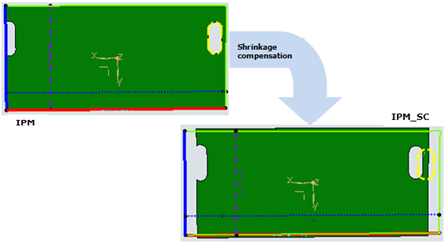
Figure below depicts the few manufacturing features in an IPM and
how they appear in IPM_SC after shrinkage compensation.
As soon as the item structure creates this generates IPMs using the two respective
commands, shrinkage item and shrinkage IPM creates for each plate. At this juncture, both
IPM and SC_IPM look similar, with whatever
manufacturing features (attachment lines, openings) that you chose to generate
automatically. Whenever you edit the manufactured item to create more features on the
IPM, these features are created also on the
SC_IPM. In the case of margin and bevel features, which are
impacting the size of the panel, these include as input for shrinkage compensation. As
consequence, the same ratio values apply to the expanded part by margin and bevel features.
You can then add shrinkage compensation to the features. Excluding margins and bevels since
these captures by editing shrinkage (Item).
Shrinkage Planning in Part Planning - Simplified Mode
There are intermediate manufacturing features created which represent the
shrinkage compensated result for plates. And these intermediate features are not mandatory
to generate the results of this app, but optional. Part Planning, Simplified Mode provides
the capability not to create dedicated transformed items and intermediate manufacturing
features.
This is only for shrinkage compensation, which consumes resources and
time but to apply shrinkage compensation to end manufacturing features directly.
It only takes the objects, which are part planned as Simplified Mode. During
Shrinkage Planning execution, it behaves as;
For Flat and Curved plate design objects.
- Shrinkage part in the manufactured item structure it does not
create a dedicated item.
- Feature Planning
- Does not create Manufacturing features that represent only shrinkage
compensation.
- Shrinkage compensation applies to the manufacturing features directly without
intermediate feature creation. Single manufacturing features exist for individual
information for fabrication, which includes shrinkage compensation and flattened.
Shrinkage Data model change: Shrinkage part and its resulting
products do not create in Simplified Mode.

Shrinkage Data model in Simplified Mode.

As the above model changes, using shrinkage planning, there are no feature containers for
the shrinkage. Unlike normal mode, the shrinkage compensation values apply to manufacturing
features directly.
Differences
- Normal mode (Current behavior without this
function):
Manufacturing features exist in both In-Process Model and Shrinkage
In-Process Model representing a single feature. For example, OuterContour: There are
two different manufacturing features under In-Process Model and Shrinkage In-Process
Model. Each of them represents an original outer shape of design data and shrinkage
compensated outer shape by applying affinity ratio.
- Simplified mode:
One manufacturing feature exists only under
In-Process Model (Flat design part case) or Flattened In-Process Model(Curved design
part case) represents fabrication information including shrinkage
compensation. For example, OuterContour: There is only one OuterContour feature
under In-Process Model (Flat design part case) or Flattened In-Process Model (Curved
design part case) which represents outer shape including shrinkage compensated
values.
Potential difference in curved design part. Shrinkage compensation
values then apply on the curved manufacturing features. And these shrinkage applied features
transfer onto the flattened result. With this function (in simplified mode), shrinkage
compensation values apply on flattened manufacturing features directly. And uses flattened
attachment lines to compute the direction and ration values.
|


