Assigning a Pin Jig Resource | ||
| ||
Click Play to watch the video:
-
From the
Authoring section of the
action bar,
click
Manage Structure Resources
 .
.
-
Click
 ,
then select Pin Jig from the table.
Note: The existing Pin Jig resource works on an Assembly of Plates. As per a new Panel model, this treats the Panel as an assembly of plates. Thus the support of a Pin Jig Resource extends to a New Panel model as well since considers it as an assembly of plates.
,
then select Pin Jig from the table.
Note: The existing Pin Jig resource works on an Assembly of Plates. As per a new Panel model, this treats the Panel as an assembly of plates. Thus the support of a Pin Jig Resource extends to a New Panel model as well since considers it as an assembly of plates. -
Select;
- Catalog Browser
 , the text appears Select or search an
object or Press ESC to exit. In the
Search window, select
Catalog from the list window. Type your catalog
name or type catalog.
, the text appears Select or search an
object or Press ESC to exit. In the
Search window, select
Catalog from the list window. Type your catalog
name or type catalog. 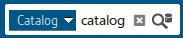
All of the catalogs appear in the search tab window.
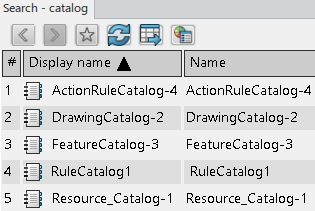
Double-click a catalog, example DrawingCatalog-2, this opens the catalog.
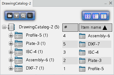
A Catalog is a tree structure consisting of the following elements:
- Chapters: A chapter references other chapters or items. Use to classify items by category.
- Items: An item is a reference to an external document or PLM Object. Items describe them with keyword values.
- Keywords: A keyword is an attribute describing a chapter or item. The Librarian can associate keywords to a chapter or item, and assign keyword values to each item. Search by keyword values to filter its content.
Libraries classify standard objects according to user-defined attributes. A Library consists of Classes, which categorize the objects in the Library hierarchy. Items are the actual objects that they manage.
Library to navigate, search, and select an item with better view and performance. The Library has a class and a description by an item.
The keyword in the catalog replaces by an attribute in the library and the filter updates accordingly.
After a resource selection, the positioning information and auxiliary viewer updates with the resource and selected manufacturing assembly.
- Catalog Browser
-
Click
Open resource in new tab
 .
A new tab appears with the resource. The part body contains the plate assembly, and a new node creates for each of the pin jig resource that contains the pins.
.
A new tab appears with the resource. The part body contains the plate assembly, and a new node creates for each of the pin jig resource that contains the pins.
