Creating a Load
This describes how to create a load parameter.
-
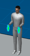
Click
Inserts a new load
 .
.
-
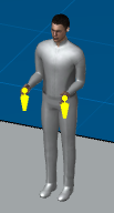
In the
Magnitude section type in
5 for the left and right hand.
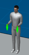
The load representations (forces acting on the hands) appears in the work area as two green arrows.
-
Expand the manikin Tree.
A description (total, right, and left force magnitudes) is under the Loads node.
 Load (Hand10.000lb;Left 5.000lb, Right
5.000lb)
Load (Hand10.000lb;Left 5.000lb, Right
5.000lb)