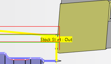
Using a Robot in the 3D Area

You can use a Robot to define extension lines, start and end limits, limit modes, location, and orientation. You can use Robot handles as precision aides. The Robot is available in all Mill-Turn Machining apps, except for Sequential Turning machining operations.

This task shows you how to:


Before you begin: You must have at least one machining operation in the manufacturing program.

Display a Robot in the 3D Area

You can use different commands to display a Robot in the 3D area.

  1. Select a turning machining operation in the Activities Process Tree.
  2. In the turning machining operation dialog box that displays, select the Geometry tab.
  3. Optional: Select Compute Input Stock to display the input stock.

  4. Right-click a section of the geometry to display the Face Selection context toolbar.
  5. Use the Face Selection context toolbar to select faces .

    Note: For more information on using the Face Wizard, see Working with the Face Wizard and Selecting Faces to Define Geometry.

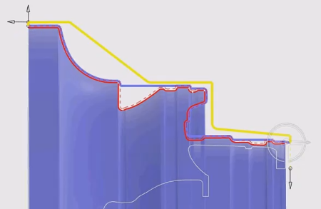
The part profile is highlighted in light blue and the rough stock profile highlighted in yellow. Four handles (two for the stock profile and two for the part profile) are displayed in the 3D area. By default, the position of the stock Start Limit Robot represents start of machining and the position of part End Limit Robot represents the end of machining.

The area formed between selected part, stock and the Robot is called the Robot area. This is a rough area where machining operation has been defined with appropriate strategic parameters. You can change the colors using Part / Stock display options in Me > Preferences > App Preferences > Simulation > Machining > NC Machining Apps Common Services > General. Part geometry is considered as hard geometry and stock geometry is considered as soft geometry by default. The default Robot position varies according to the type of machining operation.

To visualize the exact area that will be removed during the machining operation, you can use the Display Machined Area option, which displays the machining area in green. Machined area takes tool parameters, offset parameters, limit parameters with modes and tool safety angles into consideration.
Define the Robot Area

You can use a Robot to define the Robot area and limit modes for the required machining area.

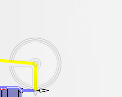
  1. Click a Robot to activate it.
    The activated Robot turns gray and displays two concentric circular areas surrounding the arrow.

  2. Select the inner circular area to:
    • Define location values using the ruler. Click the parallel triangles and slide them to the required location.
    • Define location values manually. Click the value to display and edit the text field Length.
    • Drag the Robot along the profile to the required location.
      • If an external geometry is selected, location values are treated as offset values from the midpoint of the selected geometry in the spindle plane.
      • If the Robot is inside the area defined by the profiles, the Robot area is defined by the Robot in both forward and backward directions. This can be used to limit the area radially.
      • If the Robot is outside the area defined by the profiles, the Robot area is extended from the backward projection of the Robot on the stock profile to the Robot position. If there is no projection, no Robot area solution is displayed.
    • Associate it to an external geometry (point, edge, or plane).
  3. Select the outer circle to:
    • Define the angle value using the protractor. Click the handle and slide it to the required angle.
    • Define the angle value manually. Select the value to display and edit the text field Angle.
    • Define the angle value by successively clicking the outer circle. The angle degree increases by 90° increments.
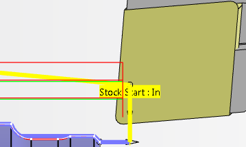
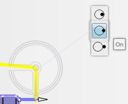
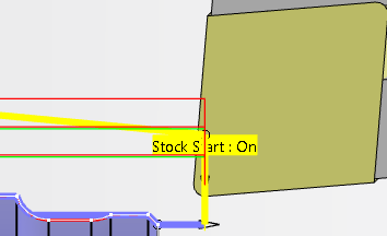
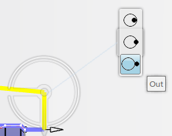
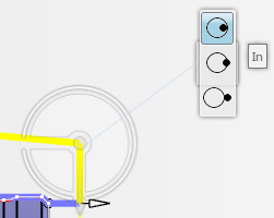
  4. Choose the limit mode by selecting one of the following from the context menu:
    • In

      which gives

    • On

      which gives

    • Out

      which gives

The machined area is defined. You can now compute the tool path for this area.

Define Location and Orientation

You can use a Robot to define location and orientation parameters for a machining operation.

  1. Right-click on the highlighted in green text under Location Arrow or Orientation Arrow.
  2. In the context menu that appears, select the required setting.

Location and orientation parameters are applied.