Using Balance and Follow Turning Operations

This section provides essential information to get the most out of Balance and Follow turning operations.

This page discusses:

Using the Balance Turning Principle

The Balance Turning operation principle is described below.

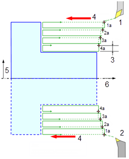
In Balance Turning operation, both tools work at the same diameter (X), the same position (Z) at twice the specified speed. The same tool path, that is "n" passes is executed by each turret. The spatial representation of Simultaneous Mode is:


  1. Turret.1
  2. Turret.2
  3. Specified depth of cut
  4. Twice Specified feed rate
  5. X
  6. Z

Note: Each pass (1a to 4a) has been intentionally shifted slightly in "Z" for clearer picture.

The temporal representation of the Simultaneous Mode is:

  1. Turret.1
  2. Turret.2
  3. Path 1
  4. Path 2
  5. Path 1'
  6. Path 2'

Using the Follow Turning Principle

The Follow Turning operation principle is described below.

In Follow Turning operation, the passes of a given tool path are shared by the two turrets. For example, even passes are assigned to the first turret (considered as the Master turret), and odd passes are assigned to the second turret (considered as the Sibling turret).

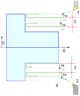
The Master turret machines at a given diameter (X), the Sibling one machines at diameter at the following path (X - 2*p). The Master turret machines at a given position (Z), the sibling one a bit behind (Z Z) with such a delay that the Sibling turret never overtakes the master one.

The spatial representation of Delayed Mode is:

  1. Turret.1
  2. Turret.2
  3. Twice Specified depth of cut
  4. + Delta "t"
  5. X
  6. Z

Note: Each pass (1a to 4a) has been intentionally shifted slightly in "Z" for clearer picture.

The temporal representation of the Delayed Mode is:

  1. Turret.1
  2. Turret.2
  3. Path 1
  4. Path 2
  5. Path 3
  6. Path 4

Common Information for Balance and Follow Turning Operations

The common information in both Balance Turning and Follow Turning operations is described below.

Tool Compatibility

Insert (type, geometry etc.) and orientation of the tool insert on both tools is exactly the same. Tool Insert holder type and Kr angle defines the symmetrical orientation of the inserts on both the tools.

Balancing operations are compatible with multi-cutter turning tools.

Insertion of Tool Change Activity

A tool change activity with the required tool is inserted under the Manufacturing Program, if tool is not compatible. A new Machining Operation is created under the new tool change activity.

The tool path of Sibling Operation become incomputable if

  • Tool change activity is deleted or modified.
  • Tool parameters of Sibling Operation are deleted or modified.

Copy of Data from Rough Turning Operation to Sibling Operation

During creating Balance and Follow turning operations, data from Strategy, Geometry, Feeds and Speeds, and Macros tabs is copied from the master Rough Turning operation to the Sibling Operation.

Note: For Macros, Copy-Transformations are applied before copying the data

If a Sibling Operation is modified, then changes are copied to the corresponding sibling Machining Operationonly.

Global View in Synchronization Wizard

The in synchronization column helps to recognize the Balance and Follow turning operations in the synchronization Global View .

Place the pointer over the Synchronization column to display tooltips for Balance and Follow turning operations.

The Synchronization editor is disabled and synchronization position for both the Machining Operations is Start-Start.

Deletion of Sibling Operations

If a Sibling Operation is deleted, a warning message appears to get confirmation. Deleting a Sibling Operation breaks all the existing links, remove synchronization, changes tool path status in Activities Process tree, and delete Balance and Follow turning operations associated with the Sibling Operation. Deleting a Sibling Operation does not delete the tool under which it was created.

Tool Path Computation

Tool path computation of master Rough Turning operation also computes tool path of its Sibling Operation. Tool path related to each Sibling Operation is stored on the corresponding master Rough Turning operation.

Tool Path Replay

The Simulate or Display occur on individual Balance and Follow turning operations. Tool path contains either even or odd paths (in case of delay).

Apt Output

Define NC_Command (NC_BALANCING) in PP word table

*START_NC_COMMAND
NC_BALANCING
%MFG_BALANCING
*END

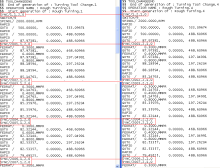
The APT output for Balance turning operation is:
Define NC_Command (NC_FOLLOWTURNING) in PP word table

*START_NC_COMMAND
 NC_FOLLOWTURNING
 %MFG_ NC_FOLLOWTURNING
 *END

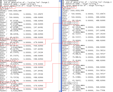
The APT output for Follow turning operation is:
Copy-Paste and Cut-Paste of Machining Operation

For copy-paste, the new pasted Machining Operation does not have the Balance and Follow turning operation parameters of the master Rough Turning operation. Pasted machining operation acts an individual Machining Operation.

For cut-paste, Balance and Follow turning operations are managed. If a Machining Operation is pasted at some location and if new location is incompatible, then the Machining Operation gets deleted. You can retrieve the deleted Machining Operation by Undo. If the location is compatible, then Machining Operation gets pasted successfully and links between the Sibling Operation gets renewed.

See Creating a Balance and Follow Turning Operationand Creating and Editing Synchronization.