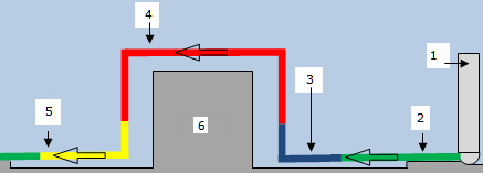
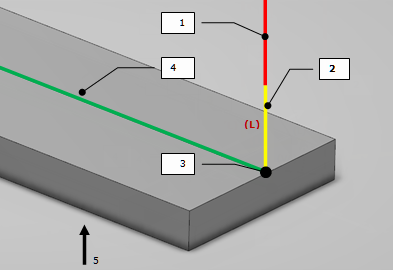
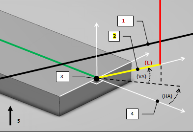
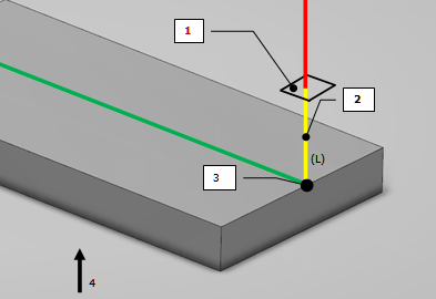
Axial Motion
This motion is a linear motion, built with:
- Length (L), defined along Tool Axis direction.
This motion is always collision free. Then it is the last solution when all NC Macro modification strategies have failed.
- Linking motion
- Axial motion
- Macro point
- Machining motion
- Tool axis
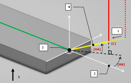
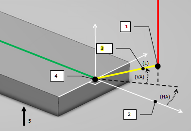
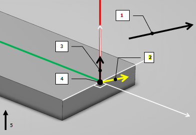
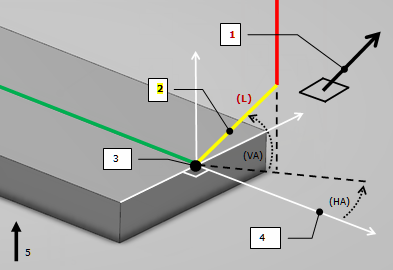
Horizontal Motion
This motion is a linear motion, built with:
- Horizontal angle (HA).
- Vertical angle (VA).
- Length (L).
In case of collision, the first step is to:
- Reduce macro length (L); the residual length, in plane, must be greater than tool diameter.
If no solution is found, a new strategy is applied:
- Horizontal angle (HA) varies around its initial value.
- If required, vertical angle (VA) is increased (up to Tool Axis).
- And length (L) can be reduced as described.
If no solution is found again, a last strategy is applied.
Axial motion is called with the following parameters: length (L) value.
- Macro reduction due to collision detection
- Tangent vector
- Macro point
- Horizontal motion
- Tool axis
Tangent Motion
This motion is a linear motion, built with:
- Tangent Vector (tangent to trajectory on macro point)
- Length (L)
If collision is detected, a new strategy is applied.
Horizontal motion is called with the following parameters:
- Horizontal angle (HA) = 0 rad.
- Vertical angle (VA) = 0 rad.
- Length (L) does not change.
- Linking motion
- Tangent motion
- Tangent vector
- Macro point
- Machining motion
- Tool axis
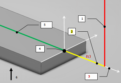
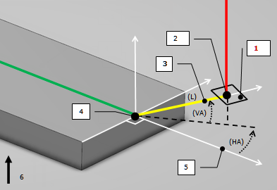
Motion to a Point
This motion is a linear motion, built with:
If collision is detected, a new strategy is applied.
Horizontal motion is called with the following parameters:
- Horizontal angle (HA) see picture.
- Vertical angle (VA) see picture.
- Length (L) distance between Macro point and Selected Point.
- Selected point
- Motion to a point
- Tangent vector
- Macro point
- Tool axis
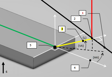
Motion to a Line
This motion is a linear motion, built with:
- Selected Line on which the Macro point will be
projected.
If collision is detected, a new strategy is applied.
Horizontal motion is called with the following parameters:
- Horizontal angle (HA) see picture.
- Vertical angle (VA) see picture.
- Length (L) distance between Macro point and projected point
- Selected Line
- Projection of macro point on the selected line
- Motion to a line
- Tangent vector
- Macro point
- Machining motion
- Tool axis
Motion Perpendicular to a Plane
This motion is a linear motion, built with:
- Selected Plane on which the Macro point will be projected.
If collision is detected, a new strategy is applied.
Horizontal motion is called with the following parameters:
- Horizontal angle (HA) see picture.
- Vertical angle (VA) see picture.
- Length (L) distance between Macro point and projected point
- Selected plane
- Projection of macro point on the selected plane
- Motion perpendicular to a plane
- Macro point
- Tangent vector
- Tool axis
Distance Along a Line Motion
This motion is a linear motion, built with:
- Selected Line that gives a direction.
- Length (L), to reach.
If collision is detected, a new strategy is applied.
Horizontal motion is called with the following parameters:
- Horizontal angle (HA) = 0 rad.
- Vertical angle (VA) = 0 rad.
- Length (L) does not change.
- Selected line
- Distance along a line motion
- Macro point
- Tangent vector
- Tool axis
Axial Motion up to a Plane
This motion is a linear motion, built with:
This motion is always collision free.
- Selected plane
- Axial motion up to a plane
- Macro point
- Tool axis
Tool Axis Motion
This motion is a linear motion, built with:
If collision is detected, Tool Axis motion varies between the selected axis and initial
tool axis to find a position without collision.
If no position is found, macro is not applied.
Note:
This behavior is the current one.
- Selected axis
- Tool axis motion
- Initial tool axis
- Macro point
- Tool axis
Normal Motion
This motion is a linear motion, built with:
- Selected Normal to a Surface
- Length (L)
If collision is detected, a new strategy is applied.
Horizontal motion is called with the following parameters:
- Horizontal angle (HA) see picture.
- Vertical angle (VA) see picture.
- Length (L) does not change.
- Selected normal to a surface
- Normal motion
- Macro point
- Tangent vector
- Tool Axis
Ramping Motion
This motion is a linear motion, built with:
- Horizontal Safety Distance (HD).
- Vertical Safety Distance (VD).
- Ramping Angle (RA).
If collision is detected, a new strategy is applied.
Axial motion is called with the following parameters:
- Length (L) = Vertical Safety Distance (VD)
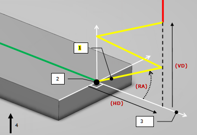
- Ramping motion
- Macro point
- Tangent vector
- Tool axis
Circular Motion
This motion is a linear motion, built with:
- Angular Sector (AS).
- Angular Orientation (AO).
- Radius (R).
If collision is detected, the first step is to:
- Increase Angular Orientation (AO) up to 90 degrees.
- Reduce Angular Sector (AS) by keeping distance in plane between macro point and arc extremity, greater than tool radius.
If no solution is found, a new strategy is applied.
Horizontal motion is called with the following parameters:
- Horizontal angle (HA) see picture.
- Vertical angle (VA) see picture.
- Length (L) see picture.
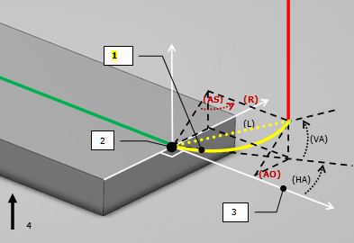
- Circular motion
- Macro point
- Tangent vector
- Tool axis
Helix Motion
This motion is a helix motion, built with:
- Radius (R)
- Height (H)
- Angle (A)
If collision is detected, the first step is to:
- Reduce macro length by keeping distance in plane between macro point and helix extremity, greater than tool radius.
If no solution is found, a new strategy is applied.
Ramping motion is called with the following parameters:
- Horizontal Safety Distance (HD) = 2 x Radius (R).
- Vertical Safety Distance (VD) = Height (H).
- Ramping Angle (RA) = Angle (A).
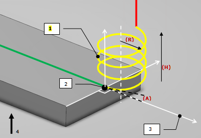
- Helix motion
- Macro point
- Tangent vector
- Tool axis
PP Word List
This motion is collision free.