Create a Lathe Insert
You can create all types of lathe inserts such as rhombic, round, square, or diamond.
This task illustrates the creation of a diamond lathe insert. Dialog box names depend on the
type of insert you create.
-
From the Setup section of the action bar, click Resource Creation
 . .
- Optional:
In the Resource Creation dialog box, click
 to search a
tool from the Tool Search panel. For more information, see Tool Search to search a
tool from the Tool Search panel. For more information, see Tool Search
-
In the Resource Creation dialog box, expand the Lathe Tools area and select a diamond lathe insert in the Lathe Inserts area.
The insert appears in the
work area with values corresponding to the default insert dimensions. 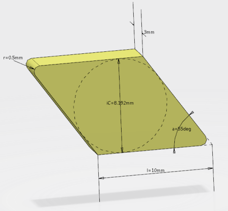 - Optional:
In the NC Resource dialog box, enter a new name and comment for the insert.
-
In the
work area, double-click a value to modify it.
-
In the Edit Parameter dialog box,
enter a new value.
- Click OK to update the insert with the new value.
- Modify other values in the same way.
- To specify other insert parameters, click Edit parameters
 . .A dialog box appears with expandable areas such as: - Geometry
- Technology
- Feeds & Speeds
- Part Body Color
-
Edit the required parameters and click OK.
- To finish, click OK in the NC Resource dialog box.
The lathe insert is created and appears in the tree under the manufacturing cell.
Create a Lathe Shank
You can create all types of lathe shanks such as external, groove external, or thread internal. This task illustrates the creation of an external lathe shank. Dialog box names depend on the type of shank you create.
-
From the Setup section of the action bar, click Resource Creation
 . .
-
In the Resource Creation dialog box, expand the Lathe Tools area and select a lathe shank in the Lathe Shanks area.
The lathe shank appears in the
work area with values corresponding to its dimensions. 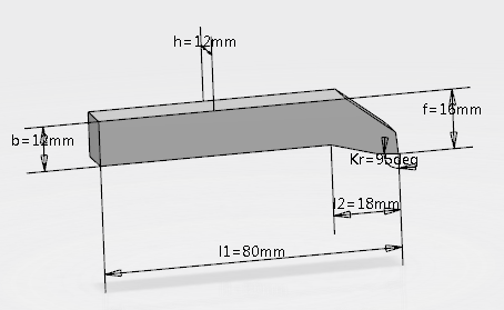 - Optional:
In the NC Resource dialog box, enter a new name and comment for the lathe shank.
-
In the
work area, double-click a value to modify it.
-
In the Edit Parameter dialog box,
enter a new value.
- Click OK to update the shank with the new value.
- Modify other values in the same way.
- To specify other lathe shank parameters, click Edit parameters
 . .A dialog box appears with expandable areas such as: - Geometry
- Technology
- Gauge Insert
- Compensation
- Attachment
- Part body color
- Y-axis Parting Tool
-
Note:
This expandable area includes the Y-axis mount
option. The top face of the insert in a y-axis parting blade is
perpendicular to the blade, so the cutting force direction is more efficient.
This results in considerably higher stability and reduced vibration.
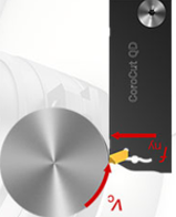
When
you check this option, a regular tool is modified with cutting forces acting
on specific areas, as shown in red below.
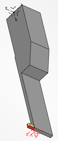
During
simulation, you must compute x,y,z offsets on the tool. In this case, turning
material removal is computed in zx plane using insert shape.
-
Modify the required parameters and click OK.
- To finish, click OK in the NC Resource dialog box.
The lathe shank is created and appears in the tree under the manufacturing cell. Notes:
- You can add a user representation to the lathe shank. See User Representation for the Tool.
- When you create a generic shank and you want to switch back to a shank with more attributes,
delete the generic shank by clicking Reject Resource
 . Then create a new shank without selecting Shank
With No Geometry. . Then create a new shank without selecting Shank
With No Geometry.
Create a Multi-Cutter Tool from Existing Lathe Tools
You can create a tool holder (multicutter tool) that can combine several lathe
tools.
Multicutter tools support prismatic holders only.
Before you begin: Create two lathe tools.
-
From the Setup section of the action bar, click Resource Creation
 . .
- In the Resource Creation dialog box, expand the Tool Assemblies area and click Creates MultiCutter Tool Assembly
 . . - Create a prismatic holder:
- In the Resource Selection dialog box, expand the Holders area and click Prismatic Holder
 . .
- Add a user representation to the holder:
- In the Prismatic Holder area of the NC Resource dialog box, click Manage Representation
 . . - In the Manage Representation dialog box, click Add User Representation.
- In the Define User Representation dialog box, click
 and search for a user representation. and search for a user representation. - In the search results, select a user representation.
- Define two base axes on the prismatic holder where the tools are to be located:
- In the Define User Representation dialog box, click Base Axis,
andBase Axis select a base axis for the first tool.
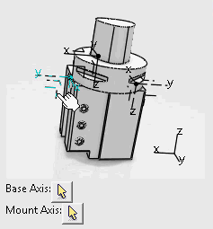
- Repeat the previous step to define another base axis for the second tool.
- Click OK to validate the two base axes.
- In the Manage Representation dialog box, click OK to validate the user representation.
- Mount the tools on the holder:
- In the Prismatic Holder area of the NC Resource dialog box, click Add Sub-Assembly
 and select a lathe tool in the tree. and select a lathe tool in the tree. - Select a base axis on the holder where you want to position the lathe tool.
The lathe tool is mounted on the holder. 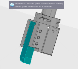 - Repeat the steps above to mount the second tool on the holder.
- Optional:
Modify the axial and radial values of the multicutter by double-clicking the values
that appear in the work area.
The multicutter tool is created. Two lathe tools are mounted on it. When you create a machining operation, you can specify which tool of the
multicutter you want to use during the operation.
|


