Defining the Tool Axis | ||
| ||
- In the
Strategy tab
of the operation, or in the machining feature dialog box,
- Click the tool axis arrow
- Alternatively, right-click the tool axis arrow, and choose Select.
- The Tool Axis dialog box is displayed.
- When Components is selected, Axial and Radial are activated.
- When Angle is selected, Angle is activated.
- The tool is displayed, at a default position, and a default orientation (0 degree angle with respect to the spindle radial axis).
In the Manual mode rulers is used to change the tool axis. To display geometrical parameters in 3D select Creating and Editing Milling, Drilling, and Probing Tools in the Tool definition dialog boxes of machining operations.
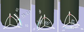
The pointer acts as a handle attached at the P9 compensation point of the tool representation.
- Place the pointer over the tool representation.The handle changes to a circular arrow that you can use to rotate the tool axis.

- Repeat those steps as necessary until the desired B axis angle is evaluated.Example:
- In the pictures below, the tool is dragged using the pointer.
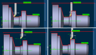
- When you release the pointer, the tool representation snaps automatically to the nearest location on the part, with the handle changing to let you rotate the tool axis.


- In the pictures below, the tool is dragged using the pointer.