Create Milling, Drilling, and Probing Tools
You can create tools such as end mills, spot drills, and ball stylus tools. This task
illustrates the creation of an end mill tool. Dialog box names depend on the type of tool you
create.
-
From the
Setup section of the action bar,
click Resource Creation
 . .
The Resource Creation dialog box appears with expandable
areas such as:
- Milling Tools
- Drilling Tools
- Probing Tools
- Optional:
In the Resource Creation dialog box, click
 to search a
tool from the Tool Search panel. For more information, see Tool Search to search a
tool from the Tool Search panel. For more information, see Tool Search
-
Expand the
Milling Tools area and select Creates End Mill
Tool
 . .
The tool appears in the work area
with values corresponding to the default tool dimensions. 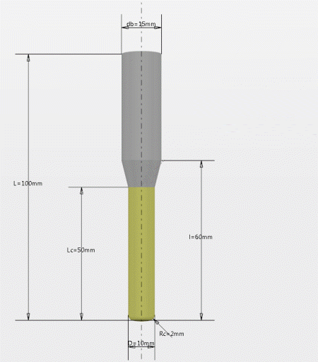 - Optional:
In the NC Resource dialog box, enter a new name and comment for
the tool.
-
In the work area,
double-click a value to modify it.
-
In the Edit Parameter dialog box, enter a new value.
-
Click OK to update the tool with the new value.
-
Modify other values in the same way.
-
To specify other
parameters of the tool, click Edit parameters
 in
the End Mill Tool area of the NC Resource
dialog box. in
the End Mill Tool area of the NC Resource
dialog box.
A dialog box appears with expandable areas such as:
- Geometry
- Technology
- Feeds & Speeds
- Compensation
- Attachment
- Part Body Color
-
To select a holder, click Add Holder then choose a holder selection
option.
-
Modify the required parameters and click OK.
-
To finish, click
OK in the NC Resource dialog box.
You created the end mill tool and it appears in the tree under the manufacturing cell. 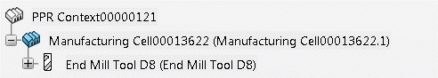
Create Mill Insert Holders
You can create an empty mill insert holder for milling and drilling items. This task
illustrates the creation of an insert holder with an end mill tool.
-
From the
Setup section of the action bar,
click Resource Creation
.
The Resource Creation dialog box appears with expandable
areas such as:
- Milling Tools
- Drilling Tools
- Probing Tools
- Optional:
In the Resource Creation dialog box, click <image> to
search a tool from the Tool Search panel. For more information, see
Tool Search
-
Expand the Milling Tools area and select Creates Mill
Insert Holder
 , then Creates End Mill Tool
. , then Creates End Mill Tool
.
The insert holder appears in the work area
with values corresponding to the default tool dimensions.
- Optional:
In the NC Resource dialog box, enter a new name and comment for
the insert holder.
-
Select the nocut user representation of the insert holder.
This contains the axis systems where the inserts can be mounted. For more information,
see Define User Representation.
-
Define the gauge insert REF to specify the compatible inserts
that can be mounted.
-
Click OK in the NC Resource dialog
box.
The end mill tool insert holder appears in the tree under the manufacturing cell. Note:
To mount inserts to the tool holder, create a tool
assembly.
Create a Multi-Diameter Drill Tool with Multiple Stages
You can create a multi-diameter drill tool with more than 3 stages.
-
From the
Setup section of the action bar,
click Resource Creation
.
The Resource Creation dialog box appears with expandable
areas such as:
- Milling Tools
- Drilling Tools
- Probing Tools
-
Expand the Drilling Tools area and select Create
Multi Diameter Drill Tool
 . .
The tool appears in the work area
with values corresponding to the default tool dimensions.
- Optional:
In the NC Resource dialog box, enter a new name and comment for
the tool.
A dialog box appears with expandable areas such as:
- Geometry
- Technology
- Feeds & Speeds
- Compensation
- Attachment
- Part Body Color
-
Expand the Geometry area, and specify the required number of
stages.
The following fields appear and are dynamically created for each additional
stage: Stage length, Stage diameter, and
Stage taper angle. Compensation correctors associated to each
stage from the fourth stage onwards appear. For the fourth stage: P10, P11, and P12
correctors appear. For the fifth stage: P13, P14, and P15 correctors
appear. Point length, Point
diameter, and Tool diameter are visible for all
stages and display the distance from the point to the mount point or tip point. These
values are calculated automatically according to the parameter inputs in the
Geometry area. -
When a user-representation is added, you can also compute the rotary profile of a
tool from the Manage Representation panel.
-
For an existing rotary representation, click Upgrade
Rotary.
Note:
The rotary part remains the same, only features inside the rotary part are
modified.
-
To create a rotary representation with the new profile computation, click
Generate Rotary.
-
To select a holder, click Add Holder then choose a holder selection
option.
-
Modify the required parameters and click OK.
-
To finish, click
OK in the NC Resource dialog box.
Edit a Tool
You can edit a tool from the manufacturing cell.
|