Selecting Faces of a Part in a Turning Operation

When defining a geometry in a turning operation, you can select a maximum of a part faces in two clicks using the Face Selection context toolbar. The context toolbar appears when you right-click the colored face of the part in the geometry tab of the operation dialog box and select By Face.


Before you begin: Click Display Option Panel in the Face Selection context toolbar and verify that the Automatic option is selected.
See Also
Face Selection for Turning Operations
  1. Select a face of the part.
  2. Select another face of the part, non-adjacent to the first one.

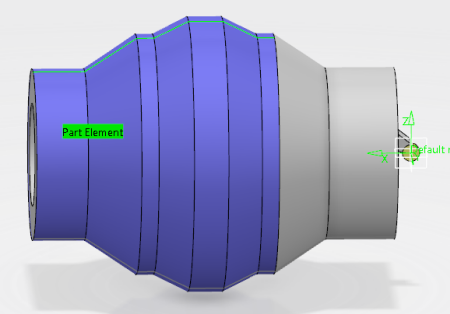
All the faces between the two selected faces are automatically selected and highlighted. The profile of the part is also highlighted.
Tips:
  • If the faces with the largest distance from the spindle axis are not automatically selected, select them manually by selecting them. This ensures that you get the maximum turning envelope of the part.
  • Do you want to display the part profile below the spindle or axial axis of the plane? Click Flip from the Face Selection context toolbar.