Using the Fault Monitor | |||
| |||
-
Click Fault Monitor
 .
The Fault Monitor Manager appears.
.
The Fault Monitor Manager appears.
- Monitoring of a specific fault can be turned ON/OFF by clicking in the Status column.
- For worker resources, it is impossible to add filtering behavior on fault types. This option is deactivated.
- On completion of simulation, the panel displays all the faults that are detected and the relevant information, Start Time, duration, cause, and others.
- Cause column also contains information about the manikin segment, which has triggered a fault during simulation.
Table 1. Fault Monitor for Worker Resource Fault Description Collision Clash of manikin body part with the surrounding objects or other manikins. DOF Travel Limit Maximum angular limits (absolute value) of each DOF. These values re predefined on the manikin. DOF Caution Zone The Lower limit of the zone with the highest score (absolute value) of each DOF, not acceptable zone. DOF Soft Limit Upper limit of the zone with the lowest score (absolute value) of each DOF, acceptable/conditionally acceptable zone. -
Select
 for the Worker
resource in 3D.
for the Worker
resource in 3D.

-
Selecting a fault result in the list view.
This synchronizes to a starting duration of that fault, which is the equivalent to pause the simulation when the resource posture is in a nonacceptable zone.
There is visual feedback in 3d (segments colored) according to fault type.
- Green depicting bend forward within acceptable DOF limits.
- Yellow depicting bend forward within conditionally acceptable DOF limits.
- Red depicting bend forward in nonacceptable DOF limits.
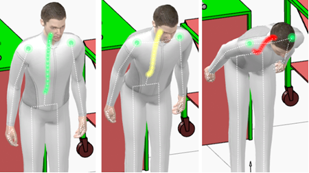
Table 2. Working Postures and Movements Trunk Bending Forward Degree of Freedom (DOF) Acceptable 0–20 degrees Conditionally acceptable 20–60 degrees Not Acceptable Less thank 60 degrees Trunk Bending Sideways Degree of Freedom (DOF) Acceptable -Trunk bending sideways or twisting not clearly visible. Less than or = 10 degrees Conditionally acceptable - Trunk bending sideways or twisting clearly visible, less than 2/min. Greater than or = 10 degrees Not Acceptable -Trunk bending sideways or twisting clearly visible, greater or = 2/min. Greater than or = 10 degrees Upper Arms Degree of Freedom (DOF) Acceptable -Upper arms angle. 0–20 degrees Acceptable -Upper arms angle, less than 2/min. 20–60 degrees Conditionally acceptable - Upper arms angle, greater or = 2/min. 20–60 degrees Not Acceptable -Upper arms angle. Greater than 60 degrees Upward/Downward line of Sight (gaze direction) Degree of Freedom (DOF) Above horizontal. Less than 0 degrees Acceptable. 0–40 degrees Conditionally acceptable - Frequency less than 2/min. Greater than 40 degrees Not Acceptable -If Static posture or Frequency greater than 2/min. Greater than 40 degrees
