- From the Surface Machining section of the action bar, click Multi-Axis Curve Machining
 . .
A Multi-Axis Curve Machining entity is added to
the manufacturing program.
The dialog box opens at the Geometry tab
 .
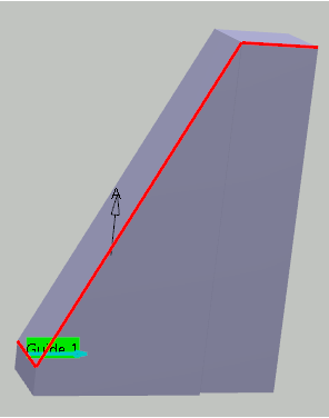
- Still in the Geometry tab, set the Curve Machining mode to Between 2 curves to drive the contact point.
- Still in the Geometry tab, click the top guiding curve in the icon. In the Edge Wizard that appears, in the option dialog box
 , set Link types to Line insert, then select edges on the part. , set Link types to Line insert, then select edges on the part. Note:
Any
gaps between the edges are filled thanks to the Insert
link option.
-
Still in the Geometry tab, set the Curve Machining type to Side to drive
the flank of the tool.
-
Go to the Strategy tab
 to specify parameters for:
- Machining
- Tool path style to Zig zag
- Machining tolerance
- Direction of cut to climb
- Sequencing to Radial first (by segment)
- Max discretization step
- Max discretization angle
- Type of contouring to Circular
- Forced contour to None
- Close contour overlap (%)
- Radial
- Distance between paths
- Number of paths
- Axial
- Maximum cut depth
- Number of levels
- Tool Axis
- Tool axis mode to Tangent axis
- Mode to Along ruling direction
- Allowed lead to 30deg
- Fanning distance to 1000mm
- Click the sensitive drive element in the icon, then select drive
surfaces in the work area.
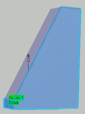
A default reference tool axis is displayed in the work area. Note:
When machining a strip (or band) for faces, the tool axis is
deduced from the isoparametrics of the faces in order to ensure
continuity of the trajectory.
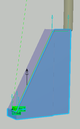
- If
needed, click the tool axis arrow
(A) in the sensitive icon, then specify a different
tool axis direction.
You can do this by selecting a surface. In
this case the surface normal is used. - Go to the Tools tab
 to select a tool. to select a tool. - Go to the Feeds and Speeds tab
 to specify the feedrates and spindle speeds for the machining operation. to specify the feedrates and spindle speeds for the machining operation.
- Go to the Macros tab
 to specify the machining operation transition paths (approach
and retract motion, for example). to specify the machining operation transition paths (approach
and retract motion, for example).
-
Click Display or
Simulate to check the validity of the machining operation.
- The tool path is computed.
- A progress indicator is displayed.
- You can cancel the tool path computation at any moment before 100% completion.
- Click OK in the Display or
Simulate dialog box, and again in the main dialog box to create the machining operation.
The tool path is created.
|