Analyzing Positioning Sensors

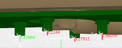
You can switch on or off sensors at a particular drilling point based on the surface geometry at the location. The upper machine head of a typical drilling or riveting machine may have several sensors (4 or 8) controlling the perpendicularity between the drilling line and panel surface. These sensors provide the necessary input to the machine to calibrate while drilling.


Before you begin:
  • Have a scenario with sensors.
  • You must define manufacturing fasteners in the manufacturing program or operation.
See Also
Managing Positioning Sensors
  1. From the Drilling Riveting section of the action bar, click Analyze Positioning Sensors .
  2. Select a manufacturing program or an operation.


    All the fastening points consumed in the operation will be considered for analysis.

  3. Select Compute to start the analysis.
    • : pauses the computation.
    • : restarts the computation from the paused point.
    • : validates the computation.
    • : cancels the computation.
    The Computation Results table appears populated with the sensor status.


  4. Select the row or fastener.


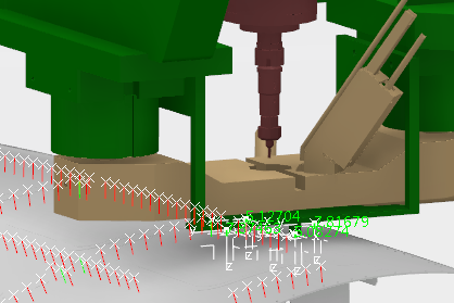
    The resource moves to the respective fastener location and the distance is shown with the distance annotation.

    Since there is a handle attached to the sensor, you can change the status of sensor in the work area by clicking on the line turns the respective sensor toggle On or Off status or by selecting in the Computation Results table.