Prismatic Machining Area Features

This section provides reference information about Prismatic Machining Area features. They is used in formulas, checks, and tool queries as well as search queries.

This page discusses:

General Information

The Prismatic Machining Area features are associative.

When running Feature Recognition, the milling areas (with non-planar top element) are taken into account for feature creation (Prismatic Machining Area). Checking is done on bottom face only, whereas conditions are not applied on top face. The top face is any surface, it does not need to be planar which is parallel to bottom face.

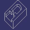
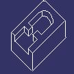
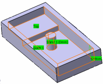
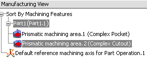
Feature recognition provides a Prismatic Machining Area corresponding to a Complex Pocket. The boundary is defined by a hard boundary only. An imaginary contour at the intersection of Hole and Slot is automatically defined to close the hard contour.

Formulas, Checks and Tool Queries

Prismatic Machining Area features is used in formulas, checks and tool queries in machining processes and machining operations (for example, to find the appropriate tool to machine the machining area). Example: Look in: MillAndDrillToolAssembly, Cutting length>Prismatic machining area.Depth or Nominal diameter<Prismatic machining area.Minimum corner radius*2

See Using Knowledge in Machining Processes

Bottom Color Attribute for Prismatic Machining Area feature

The Bottom Color is the new parameter in the Machining Area Parameters dialog box. The Bottom Color parameter value gets updated after you select the bottom in 3DEXPERIENCE platform for Prismatic Machining Area feature. The value of Bottom Color parameter is in form of RGB value and is stored as string. The format/syntax of value is: (Red value, Green value, and Blue value).

If bottom is not selected for Prismatic Machining Area feature then the Bottom Color parameter in the Machining Area Parameters dialog box attribute is displayed as NONE.

Note: Bottom Color parameter is added only for newly created Prismatic Machining Area feature and is not available for previously created and saved Prismatic Machining Area feature.

In case, if you change the color of the bottom in 3DEXPERIENCE platform, then you have to edit the Prismatic Machining area feature dialog box to get the updated value of the Bottom Color parameter.

Bottom Color parameter is available in knowledgeware expressions such as "formula" and "checks" for different operations in machining process. It is seen from formula in Knowledge action bar for respective Prismatic Machining Area feature.

Associativity of Prismatic Machining Areas

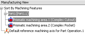
A Prismatic Machining Area in the Manufacturing View has associated geometry in the part. Typical geometry could be:

  • Top element
  • Bottom element
  • Boundary profile
  • Other Prismatic Machining Area parameters such as minimum corner radius.

If the geometry is modified in the part document, then corresponding parameters and surface information for Prismatic Machining Area are updated in Manufacturing View to reflect correct values.

Note: Some geometry modifications to a part can change the feature type. For example:
  • the depth of complex pocket is changed so that it becomes complex cutout
  • the boundary profile of a complex pocket is modified in such a way that it becomes a complex step, blind slot or through slot.

Such changes are not associative.

Supported Machinable Features Type

The prismatic machinable features type are described below.

Complex Pocket

A complex pocket is a closed multi-sided recess.

Specifications on part Results in Prismatic Machining Area
  • A bottom stamp as a hard stamp
  • A top element as a top limit
  • A boundary comprising a series of ordered faces.
  • A depth from top to bottom
  • A minimum corner radius
  • A minimum channel width
  • A maximum channel width
  • A top plane
  • A bottom plane
  • A wire frame contour.

Complex Step

A complex step is an open multi-sided recess.

Specifications on part Results in Prismatic Machining Area
  • A bottom stamp as a hard stamp
  • A top element as a top limit
  • A boundary comprising a series of ordered faces with hard and soft qualifications.
  • A depth from top to bottom
  • A minimum corner radius
  • A minimum channel width
  • A maximum channel width
  • A top plane
  • A bottom plane
  • A wire frame contour with a series of elements qualified as soft and hard.

Through Slot

A through slot is a specific step whose contour is two parallel faces as a hard boundary and two other faces as limits.

Specifications on part Results in Prismatic Machining Area
  • A bottom stamp as a hard stamp
  • A top element as a top limit
  • A boundary comprising a series of 4 ordered faces with hard and soft qualifications.
  • A minimum corner radius
  • A minimum channel width
  • A maximum channel width
  • A top plane
  • A bottom plane
  • A wireframe contour with 4 elements: 2 lines and two other elements.

Blind Slot

A blind slot is a specific step with two parallel lines and a corner between them. It has an open boundary.

Specifications on part Results in Prismatic Machining Area
  • A bottom stamp as a hard stamp
  • A top element as a top limit
  • A boundary comprising a series of 4 ordered faces with hard and soft qualifications.
  • A depth from top to bottom
  • A minimum corner radius
  • A minimum channel width
  • A maximum channel width
  • A top plane
  • A bottom plane
  • A wireframe contour with 4 elements: 2 lines, 1 half circle and one other element.

Complex Cutout

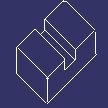
A complex cutout is a multi-sided opening through the part.

Specifications on part Results in Prismatic Machining Area
  • A bottom element as a bottom limit
  • A top element as a top limit
  • A boundary comprising a series of ordered faces.
  • A depth from top to bottom
  • A minimum corner radius
  • A minimum channel width
  • A maximum channel width
  • A top plane
  • A bottom plane
  • A wireframe contour.

Islands

Islands can be recognized and associated to Pocket and Step type machinable features. Islands is associated to features without necessarily sharing a bottom face.

Islands is included Pocket and Step type machinable features.

See examples below:


Specifications on part Results in Prismatic Machining Area
  • A bottom stamp as a hard stamp
  • A top element as a top limit
  • A boundary comprising a series of ordered faces.
  • A depth from top to bottom
  • A top plane
  • A bottom plane
  • A wireframe contour.