Probing Operations | ||
| ||
PP Table
Strategy and geometry parameters for Probing operations are described in PP Tables and Word Syntaxes - PP Word Tables
Strategy for Holes or Pins Probing
- Tool axis
- Select tool
axis in the 3DEXPERIENCE platform.
By default, the value is 0., 0., 1.
- Probing direction
- Specifies direction of the first probing.
By default, the value is 1., 0., 0.
- Probing Tolerance
- Specifies probing tolerance used in the computation of the tool path.
- Depth of contact
- Specifies depth of penetration of the stylus into the material.
- Number of Probes
- Specifies number of probing points.
By default, the value is 4.
The value must be greater than 0.
- Safety Distance
- Specifies safety distance.
By default, the value is 10.mm.
- Depth
- Specifies depth
distance.
By default, the value is 0.mm, if you select points.
- Security Distance
- Specifies distance before contact with part
to change the feedrate in probing feedrate.
By default, the value is 5.mm.
- Compensation and Compensation Application mode
- This
specifies how the Compensation, or in other words the corrector type
specified on the tool (P1, P2, P3, for example) is used to define the
position of the tool: Output point (the tool compensation point is generated
in the output file. The tool path computation is done according to the tool
tip) or Guiding point (the tool motion is computed according to the tool
compensation point and the tool compensation point is generated in the
output file).
If the type of the user parameter is Multi values, the generated value of your parameter is changed for each point, except in these cases:
- if the linking macros of the probing operation are deactivated. In this case, only one NC CYCLE is generated. The generated value of the user parameter is the first value.
- if the Output Cycle syntax of NC Data Option is deactivated. In this case, the generated value of your parameter is the first value.
Note: This last parameter, Guiding point is not available in MultiPoint Probing, because the generated point in the cycle command is always the point to probe, never the tip or center tool.Note: The tool compensation point is defined on the tool and used on the operation.The Compensation app mode defines the tool position to reach.
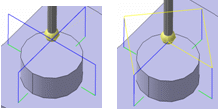
- Return by the middle
- When selected, after each probe, the retract goes through the middle of the
hole (or the pin). Example when the option is activated then
deactivated:
- Return by the top plane
-
- Is available only when Probing Side is set to Probe Inside.
- When selected, after each probe, the retract goes through the top plane.
Geometry for Holes or Pins Probing
- Probing Side
- List of
geometries composed of points (center of holes or pins to probe) or guides
(contour of holes or pins). You can select points, circles, and cylinders.
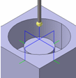
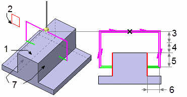
- Probe Inside to probe a hole,
1-Top plane, 2-Selected point, 3-Safety distance, 4-Offset on top plane, 5-Depth distance, 6-Security distance
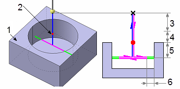
- or Probe Outside to probe a pin.

1-Top plane, 2-Selected contour, 3-Safety distance, 4-Offset on top plane, 5-Depth distance, 6-Security distance
- Probe Inside to probe a hole,
- Diameter
- Specifies diameter.
Double-click Diameter and edit it in the dialog box that appears.
By default, the value is 0.mm.
- Angle
- Specifies
angle.
Double-click Angle and edit it in the dialog box that appears.
- Top\Part\Points
- Select top, part,
and plane in the 3DEXPERIENCE platform.
You can:
- remove your selection and select a new contour, Remove, Analyze
- Modify the geometry, hence the diameter or the angle, and retrieve the associativity via the context menu: Restore Associativity
Note: If the contour of the hole (or pin) is selected, the diameter is automatically computed and is associated with the geometry. Its value is displayed in the sensitive icon. - Offset on Part
- Specifies
offset on part.
By default, the value is 0.
Strategy for Slots or Ribs Probing
- Tool axis
- Select tool
axis in the 3DEXPERIENCE platform.
By default, the value is 0., 0., 1.
- Probing direction
- Specifies direction of the first
probing.
By default, the value is 1., 0., 0.
- Probing Tolerance
- Specifies probing tolerance used in the computation of the tool path.
- Depth of Contact
- Specifies depth of penetration of the stylus into the material.
- Safety Distance
- Specifies safety distance.
By default, the value is 10.mm.
- Depth
- Specifies
depth distance.
By default, the value is 0.mm.
- Security Distance
- Specifies distance before contact with part
to change the feedrate in probing feedrate.
By default, the value is 5.mm.
- Compensation and Compensation Application mode
- See Compensation and Compensation Application mode under Strategy for Holes or Pins Probing
- Return by the top plane
-
- Is available only when Probing Side is set to Probe Inside.
- When selected, after each probe, the retract goes through the top plane.
Geometry for Slots or Ribs Probing
In addition to the two faces or planes which compose the Slot or the Rib, you can define the following.
- Probing Side
- Specifics the probing side.
You can specify:
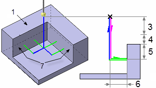
- Probe Inside to probe a slot,
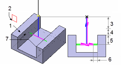
1-Top plane, 2-Selected plane, 3-Safety distance, 4-Offset on top plane, 5-Depth distance, 6-Security distance, 7-Selected faces
- or Probe Outside to probe a rib.
1-Top plane, 2-Selected plane, 3-Safety distance, 4-Offset on top plane, 5-Depth distance, 6-Security distance, 7-Selected faces
- Probe Inside to probe a slot,
- Offset on Part
- Specifies
offset on part.
By default, the value is 0.
- Width
- Specifies width. Its value is displayed in the
sensitive icon.
Double-click Width and edit it in the dialog box that appears.
By default, the value is 0.
- Top\Planes\Part\Faces
- Right-click to select top\planes\part\faces in the 3DEXPERIENCE platform.
You can
- remove your selection and select new faces, Analyze,
- Modify the geometry, hence the rib or the slot, and retrieve the associativity via the context menu: Restore Associativity.
Strategy for Corner Probing
- Tool axis
- Select tool
axis in the 3DEXPERIENCE platform.
By default, the value is 0., 0., 1.
- Probing Tolerance
- Specifies probing tolerance used in the computation of the tool path.
- Depth of contact
- Specifies depth of penetration of the stylus into the material.
- Distance of first point
- Defines the distance between the corner and the
first probing point for the external corner.Note: For the internal corner, the distance between the corner and the first probing point is designed by this distance plus the security distance.
- Distance of second point
- Defines the distance between the first and the second probing points.
- Safety Distance
- Specifies safety distance.
By default, the value is 10.mm.
- Depth
- Specifies
depth distance.
By default, the value is 0.mm.
- Security Distance
- Specifies distance before contact with part
to change the Feedrates in probing Feedrates.
By default, the value is 5.mm.
- Compensation and Compensation Application mode
- See Compensation and Compensation Application mode under Strategy for Holes or Pins Probing
Geometry for Corner Probing
In addition to the two faces which compose the corner, you can define the following, Probing Side:
- Probing Side
- Specifies probing side.
You can specify:
- Probe Inside to probe a internal
corner,
1-Top plane, 3-Safety distance, 4-Offset on top plane, 5-Depth distance, 6-Security distance, 7-Selected faces
- or Probe Outside to probe an external
corner.

1-Top plane, 3-Safety distance, 4-Offset on top plane, 5-Depth distance, 6-Security distance, 7-Selected faces
- Probe Inside to probe a internal
corner,
- Offset on Part
- Specifies offset on part.
By default, the value is 0.
- Top plane/Faces/Part
- Select top plane/faces/part in the 3DEXPERIENCE platform.
Strategy for Multi-Points Probing
- Tool axis
- Select tool
axis in the 3DEXPERIENCE platform.
By default, the value is 0., 0., 1.
- Probing Tolerance
- Specifies probing tolerance used in the computation of the tool path.
- Depth of contact
- Specifies depth of penetration of the stylus into the material.
- Safety Distance
- Specifies safety distance.
By default, the value is 10.mm.
- Security Distance
- Specifies distance before contact with part
to change the feedrate in probing feedrate.
By default, the value is 5.mm.
- Compensation and Compensation Application mode
- See Compensation and Compensation Application mode under Strategy for Holes or Pins Probing
Geometry for Multi-Points Probing
You can define the points to probe and their direction (1- Safety distance, 2-
Security distance).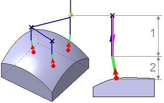
You can:
- select points, in this case their direction is the tool axis.
- pick points on a surface(or a STL mesh). At each pick, a point is created on the surface (or on the mesh) with the coordinates of pointer. This point is not associated of the face (or on the mesh): if the face (or on the mesh) is modified, the point cannot be modified. The direction of the point is the normal to the surface.
The points selected are displayed under the geometry sensitive icon showing the Number, Coordinates, and Direction. You can:
- Edit Coordinates
 modifies probing point coordinates,
 - Edit Direction
 modifies probing point direction,
 - Remove
 removes,
 - Up, Down

 reorder's
them.
reorder's
them.
Right-click the number and you can activate the context menu to select Normal to Part which allows you to select the normal to part direction or keep the one explicitly defined. The default value is the explicit direction. Multi-selection of points is supported.
Select a number, and click Edit Coordinates the Modification Coordinates dialog
box appears, showing the coordinates. Edit accordingly, and select
OK. This adjusts the Coordinates in the list and in the work area.
Select a number, and click Edit Direction the Probing Direction dialog box
appears, showing the coordinates. Edit accordingly, and select
OK.
Probing User Parameters
This tab page is found in each probing command and works as described in Adding a User Parameter.
Probing User parameters is of the following types:
- String,
- Boolean,
- Integer,
- Real,
- Length,
- Angle.
Clicking on Add
 the
Add User Parameter dialog box appears. Enter the
appropriate information, and OK.
the
Add User Parameter dialog box appears. Enter the
appropriate information, and OK.
If the type of the user parameter is Multi values, the generated value of your parameter is changed for each point, except in these cases:
- if the linking macros of the probing operation are deactivated. In this case, only one NC CYCLE is generated. The generated value of the user parameter is the first value.
- if the Output Cycle syntax of NC Data Option is deactivated. In this case, the generated value of your parameter is the first value.
In the dialog box, right-click the Parameter in the Label list for the context menu.
Set Multiple Vales, or Reset Multiple Values
When multiples vales are selected you can add (or remove a line) to set a value for a
specific point.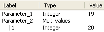
Selecting the parameter and select the Reset Multiple Values to reset the values of that parameter.
If there is more selected points than values, a warning message appears during the computation of the tool path.
For integer type parameter only, there is no need to set explicitly a value for each point.
| Tips:
Two cases: First case: If the law is defined: origin + step. Example, If you set the value for the first 2 points and not for the point 3, the user parameter is set automatically for the 3rd point according to following rule: value 2nd point = (value 2nd point - value 1st point) Example 1 2 (defined by you) 3 4 5 6 7 (defined automatically) Second Case: If the law cannot be defined, the pattern is repeated. Example: 1 2 1 (defined by you) 1 2 1 1 2 1 (defined automatically) |
Feedrates and Speeds
- Feedrate
- Transition
- You can locally set the feedrate for a transition path to a
machining operation B from a
machining operation A or from a tool change activity. This is
done by selecting the Transition check box in the Machining
Operation dialog box for operation B.
For more information, please refer to the Setting a Transition Feedrate.
- Compute: Feeds and speeds of the operation is updated according to tooling feeds and speeds by clicking the Compute button located in the Feeds and Speeds tab of the operation.
Tools
The tools used with the probing operations are Ball Stylus
 (or disc stylus: portion of a sphere) and
Cylinder Stylus
(or disc stylus: portion of a sphere) and
Cylinder Stylus
 :
:
NC Macros
For more information, please refer to the Defining Macros.
You can define transition paths in your machining operations by means of NC macros:
- Approach: to approach the operation start point (deactivated by default),
- Retract: to retract from the operation end point (deactivated by default),
- Linking: to link two probing cycles (deactivated by default).
- Clearance to avoid a fixture, for example. Note: A Clearance macro is used only if Linking macros are used.
The macros generated in APT file are managed as the drilling operations. Examples:
- Hole probing of two holes with the Linking macros deactivated:

1-Top plane, 2-Approach, 3-Retract, 4-Safety distance, 5-Offset on top plane, 6-Depth distance, 7-Security distance.
- Strategy Parameters:
- Diameter = 40mm
- Safety Distance = 10mm
- Offset on Top Plane = 2mm
- Depth = 20mm
- Security Distance = 5mm
- Macro Parameters:
- Along Tool Axis - 20mm
- Linking: Deactivated
- Retract: Along Tool Axis - 20mm
- Approach:
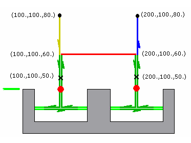
- APT
Generated:
$$ Start generation of: Holes Probing.1
RAPID
GOTO / 100.0, 100.0, 80.0, 0.0, 0.0, 1.0
FEDRAT/ 300.0000,MMPM
GOTO / 100.0, 100.0, 60.0, 0.0, 0.0, 1.0
CYCLE/PROBING_HOLE, 40.000000, 10.000000, 2.000000, 20.000000,
5.000000
GOTO / 100.0, 100.0, 50.0, 0.0, 0.0, 1.0
GOTO / 200.0, 100.0, 50.0, 0.0, 0.0, 1.0
CYCLE/OFF
FEDRAT/ 1000.0000,MMPM
GOTO / 200.0, 100.0, 80.0, 0.0, 0.0, 1.0
$$ End of generation of: Holes Probing.1
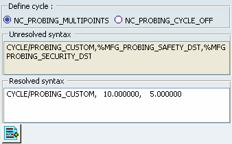
 Edit Cycle Macro
-
Clicking Edit cycle, a panel is displayed, allowing
you to edit the NC_PROBING_MULTIPOINTS instruction or the
NC_PROBING_CYCLE_OFF instructions.
 Add PP word list
- lets
you add PP Words. General information about PP Words is found in
PP Tables and Word Syntaxes - PP Word Tables.
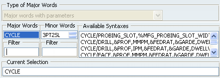
See Defining Macros for more information. The syntaxes available are:
|
Probing operation |
Available syntaxes (where n is a number: 1,2, etc.) |
 Holes or Pins Probing |
NC_PROBING_HOLE NC_PROBING_PIN NC_PROBING_HOLE_n NC_PROBING_PIN_n |
 Slots or Ribs Probing |
NC_PROBING_SLOT NC_PROBING_RIB NC_PROBING_SLOT_n NC_PROBING_RIB_n |
 Corner Probing |
NC_PROBING_CORNER NC_PROGING_CORNER_n |
 Multi-Points Probing |
NC_PROBING_MULTI_POINTS NC_PROBING_MULTI_POINTS_n |