General Information
The below example shows the use of Axial Machinable
Features.
Search Queries
Axial Machinable Features is used in search queries.
Associativity of Machinable Axial Features
Machinable Axial Features are associative after a design
change (modification, move or delete) of the shape referenced by the feature.
This is best illustrated by the two following scenarios.
- Case 1: Modifying or Moving Faces
Possible design changes by modifying
or moving faces are:
- Case 2: Removing Faces of a Shape
The design change is made by
removing faces of a shape referenced by a Machinable
Axial Feature from the Design Part. When
updating the status of any Drilling operation
referencing a Machinable Axial Feature, a
Geometry Not Found status is displayed on
the operation in the Activities tree.
Note:
Replay is not available in this case.
Supported Types of Holes
A number of hole types are supported. They are identified according to the
evaluation of the Hole type attribute as follows.
Simple Hole
The holes is Threaded Holes
A simple hole is characterized by:
- origin point and direction
- hole depth and diameter
- extension type identified according to
the evaluation of the Hole Extension attribute:
- for blind holes, bottom type identified according to the evaluation of the
Hole bottom type attribute:
- for V-bottom holes, bottom angle identified according to the value of the
Hole bottom angle attribute.
Tapered Hole
A tapered hole is characterized by:
- origin point and direction
- hole depth, diameter and angle
- extension type identified according to the evaluation of the
Hole Extension attribute:
- for blind holes, bottom type identified according to the evaluation of
the Hole bottom type attribute:
- for V-bottom holes, bottom angle identified according to the value of
the Hole bottom angle attribute.
Counterbored Hole
The holes is Threaded Holes
A counterbored hole is characterized by:
- origin point and direction
- hole depth and diameter
- counterbored depth and diameter
- extension type identified according to the evaluation of the Hole
Extension attribute:
- for blind holes, bottom type identified according to the evaluation of the
Hole bottom type attribute:
- for V-bottom holes, bottom angle identified according to the value of the
Hole bottom angle attribute.
Counterdrilled Hole
The holes is Threaded Holes:
A counterdrilled hole is characterized by:
- origin point and direction
- hole depth and diameter
- countersunk angle
- counterbored depth and diameter
- extension type identified according to the evaluation of the Hole
Extension attribute:
- for blind holes, bottom type identified according to the evaluation of the
Hole bottom type attribute:
- for V-bottom holes, bottom angle identified according to the value of the
Hole bottom angle attribute.
Countersunk Hole
The holes is Threaded Holes:
A countersunk hole is characterized by:
- origin point and direction
- hole depth and diameter
- countersunk angle and diameter
- countersunk depth
- extension type identified according to the evaluation of the Hole
Extension attribute:
- for blind holes, bottom type identified according to the evaluation of the
Hole bottom type attribute:
- for V-bottom holes, bottom angle identified according to the value of the
Hole bottom angle attribute.
Note:
The Countersunk depth is obtained by means of the
following formula:Countersunk depth = (Countersunk diameter-Hole
diameter)/(2*tan(Countersunk angle/2))
Threaded Holes
The following attributes on the axial machinable feature allow you to access
threaded hole information (in the Search function, machining process definition,
machining operations that require thread information, and so on).
- Threaded: True or False
- Thread diameter (length value)
- Thread depth (length value)
- Pitch (length value)
- Thread direction: 0 = Right-threaded 1 = Left-threaded
The attribute values are read from the design threaded hole (i.e., as
specification).
Co-axial Hole Merge Capabilities
Co-axial holes is merged automatically with the Global Feature
Recognition command. Additional merge possibilities are
available using the Manufacturing View.
The following check boxes in the Global Feature
Recognition dialog box provide a number of new capabilities for
automatically merging co-axial holes such as Automatic Merge of
Co-Axial Holes, Merge Co-Axial Holes and
Holes with same diameter, One blind hole needed
These capabilities are illustrated by considering the following three cases:
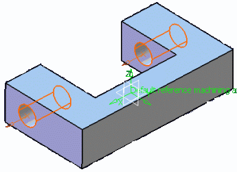
- Case 1: In the figure below, both the holes are through holes. In
previous versions, these holes could not be merged automatically due to
absence of a blind hole.

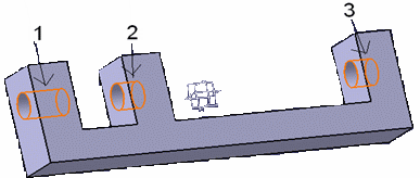
- Case 2: In the figure below, hole 1 is a through hole and the other two
co-axial holes are blind. In previous versions, automatic merge of hole
1 and hole 2 was not possible due to the presence of the two co-axial
blind holes.

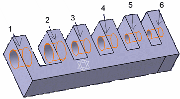
- Case 3: In the figure below, hole 1 and hole 2 have the same diameter
(40 mm), hole 3 and hole 4 have same diameter (30 mm), and hole 5 and
hole 6 have the same diameter (20 mm). In previous versions, holes with
different holes could not be merged.

The table below shows which these cases is processed using the different
combinations of the check boxes in the Global Feature
Recognition dialog box.
| Check box selection |
Case 1 |
Case 2 |
Case 3 |
|
Merge Co-axial Holes and One
blind hole needed and Holes with same
diameter
|
No |
Yes |
No |
|
Merge Co-axial Holes and One
blind hole needed |
No |
Yes |
Yes |
|
Merge Co-axial Holes and Holes
with same diameter
|
Yes |
Yes |
No |
|
Merge Co-axial Holes only |
Yes |
Yes |
Yes |
Machining Patterns of Machinable Axial Features
This section provides reference information about machining patterns of Machinable Axial Features.
Geometry Considerations for Pattern Creation
Pattern creation operates on a set of axial features selected from the
Manufacturing View, a set of faces, or an entire body.
- For a set of axial features, pattern creation applies the matching criteria
only to that set of features.
- For a set of planar faces, pattern creation applies the matching criteria to
all axial features from each face in the set. Note that all features in a
pattern have identical axes. If a reference direction is defined, the
matching criteria only applies to axial machinable features parallel to this
axis.
- For a set of non-planar faces, pattern creation applies the matching
criteria to all axial features from each face in the set. Features in the
pattern can have different axes. If a reference direction is defined,
automatic pattern creation only applies to axial machinable features
parallel to this axis.
- For a body, pattern creation applies the matching criteria to all axial
features. Note that all features in a pattern have identical axes. If a
reference direction is defined, automatic pattern creation only applies to
axial machinable features parallel to this axis.
Using Tolerances in Pattern Creation
You can retrieve the fitting tolerances defined in design features when Machinable Axial Features are created and match these tolerance values in the pattern creation functionality:
- The Tolerance Value check box lets you match the
fitting tolerance for pattern creation.
- You can create patterns of holes having same tolerance values. Matching
is done for both tabulated (H7, and so on) as well as minimum/maximum
tolerance values.
- Features having the same tolerance values are grouped in the same
pattern. Other holes, for which the tolerance value is not defined, form
a separate pattern.
- The fitting tolerance value is displayed in the dialog box of the
Machinable axial feature and in the Manufacturing View on a created
pattern.
Pattern Creation with Color Criteria
When you select the Color check box for pattern creation,
colors of holes are matched for creating patterns. The color of the axial machining feature faces is taken into account
for pattern creation.
This color may be a basic color or a RGB color (Red, Green, Blue value).
All holes have a color. When no specific color is defined on the faces, the face
color is the same than the body color.
- If only the Color check box is selected then all the
holes with same machining axis and having same color form a pattern. This
behavior is similar to other pattern creation options. For all the pattern
creation options a created pattern have holes with same machining axes.
Exception to this is holes having non-planar top faces. When there are some
holes having non-planar top faces and if none of the holes have the axis
same as any of the planar holes, then these holes can form a single pattern
even if their axes do not match.
- If other criteria are also selected along with color then holes matching all
the other criteria and color form one pattern.
- If only color is selected and machining direction is specified, then all the
holes having axis parallel to machining direction and having same color form
one pattern. Holes, which do not have axis parallel to machining direction,
does not form any pattern.
- If the holes have more than one color, these holes come under a separate
pattern for that specific orientation.
Example of Part with counterbored holes (same hole and counterbored diameters):
- Ten counterbored without specific color
- Ten counterbored (all faces in red)
- Ten counterbored (first diameter face in blue, second diameter face in red,
other faces without specific color).
Example of Hole with more than one color is taken into account in a specific
pattern. Three patterns are created:
- pattern for the undefined color (10 holes)
- pattern for the red color (10 holes)
- pattern for the holes with more than 1 color (10 holes)
Note:
If you have selected the color option for pattern, RGB color definition is
added at the end of pattern name as Color (R value, G value, B
value).
Creating Machining Patterns Automatically
You can create machining patterns automatically during global feature
recognition in the Machinable Axial Features.
Additionally Machining Pattern is created by using command Machining Pattern in
Machining Features action bar.
Initially the permanent representations of Machining Patterns are "Hidden". Make
them visible by selecting Show option in the context menu of the Pattern in manufacturing view. You can also make all the patterns
visible by selecting all patterns and select Show on
Right-clicking. You can also hide permanent representation of Machining Pattern
through selection of Hide/Show menu item in context menu on Right-click the pattern in the 3D viewer.
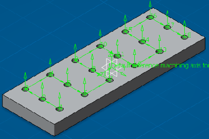
Following Representation elements is used for permanent representations of a
Machining Pattern.
- Entry point (hole origin)
- Entry vector (hole direction)
- Text Showing Position
- Connecting vector between positions
The Green color is used for the permanent representations of a Machining Pattern.

Permanent representations of Machining Patterns in the 3d viewer is selected by
clicking on the existing command NO point in the geometry
panel of manufacturing axial operations.
|


