2.5 to 5-Axis Drilling Operations Parameters

2.5 to 5-Axis Drilling Operations share common parameters or capabilities described below.

This page discusses:

Strategy Parameters for Axial Machining Operations

Strategy parameters are managed in the Strategy tab.

Power

There are different Power values for different operations under a single tool change. You can output this Power syntax in the APT source for the operation and use this output in setting up the machine, to use the full potential of multi-task drill tool holders, and effectively improve productivity and performance.

Option Manufacturing attribute
From Tool Assembly This value is output as DEFAULT for MFG_MO_TOOL_POW
Fixed This value is output as TURN for MFG_MO_TOOL_POW.
Powered This value is output as MILL for MFG_MO_TOOL_POW
Note: If you wants to use the functionality as it was, set the Power option of the operation to From Tool Assembly. If you select any option other than From Tool Assembly and outputs the MFG_MO_TOOL_POW parameter in Apt source, then you get the Power value selected in the operation output in Apt source irrespective to the Power value selected in the Tool assembly

See 2.5 to 5-Axis Drilling Operations Dialog Box for more information.

Other General Strategy Parameters

The contents of the dialog boxes may vary from the example shown above.

Option Manufacturing Attribute
Approach clearance (A) MFG_CLEAR_TIP
Approach clearance 2 (A2) MFG_CLEAR_TIP_2
Breakthrough (B) MFG_BREAKTHROUGH
Plunge mode MFG_PLUNGE_MODE
Plunge offset (Po) MFG_PLUNGE_OFFST
Plunge diameter (Pd) MFG_PLUNGE_DIAMETER.
Plunge tip (Pt) MFG_PLUNGE_TIP
Plunge for chamfering -
Depth mode MFG_DEPTH_MODE
Dwell mode -
Shift mode -
Max depth of cut (Dc) MFG_AXIAL_DEPTH
Retract MFG_RETRACT_CLEAR_TIP
Retract offset (Or) MFG_OFFSET_RET
Decrement rate MFG_DEPTH_DEC
Decrement limit MFG_DEPTH_LIM
DeepHole LeadIn NC_DEEPHOLE_LEADIN
DeepHole LeadOut NC_DEEPHOLE_LEADOUT
Automatic ROTABL ROTABL/
Output CYCLE syntax -
First compensation -
Second compensation -
Compensation application mode -
Helix mode MFG_HELIX_MODE.
Note: To generate a correct APT output for DeepHole LeadIn and DeepHole LeadOut, clear the Output CYCLE syntax check box.

Toolpath Computation and Compensation Application Mode

The tool path computation depends on the Compensation application mode options.

Toolpath Computation and Output Point

If the Compensation application mode is set to Output point, the Depth mode option (Tip/Shoulder or Distance/Diameter) is taken into account for the tool path computation.

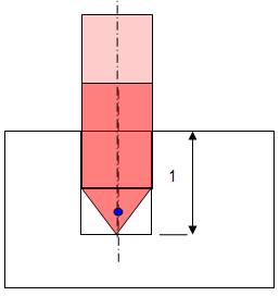
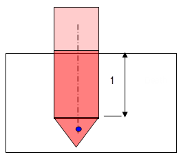
P2 compensation is defined on the tool and used on the drilling operation. The Compensation application mode is Output point. The active compensation point (blue dot in figures below) is used as the output point in the generated file (APT source).

  • Depth mode = By tip

  • Depth mode = By shoulder

Toolpath Computation and Guiding Point

When the Compensation application mode is set to Guiding point, the tool compensation point selected on the operation is taken into account to respect the depth to machine on the operation.

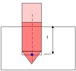
All the points to reach with the tool are computed with respect to the active compensation point. In this case Depth mode (Tip/Shoulder or Distance/Diameter) is no longer taken into account. Only the tool compensation point is used to compute the different tool positions to reach during the cycle.

P2 compensation is defined on the tool and used on the drilling operation. The compensation app mode is Guiding point. The active compensation point is represented by the blue dot in figures below:


If the Compensation application mode is set to Output point, the tool path is computed without modification: the Depth mode option (Tip/Shoulder or Distance/Diameter) is applied, if it exists on the operation.

Tool Path Output

For the GOTO statements output:

  • The tool compensation point is always generated in the output file.
  • There is no influence of the Output point or Guiding point option.

Output File Generation

%MFG_TOTAL_DEPTH and %MFG_TOTAL_DEPTH_COMP are computed parameters and depend on the Compensation application mode defined on the operation (if Compensation application mode is set to Guiding point).

  • MFG_TOTAL_DEPTH: Total depth machined by the operation. This includes the hole depth, breakthrough, and tool tip length.
  • MFG_TOTAL_DEPTH_COMP: Total depth machined by the operation up to the tool compensation point selected for the operation. This includes hole depth, breakthrough and tool tip length up to the compensation point.

The parameter %MFG_COMPENSATION_MODE (1: output point / 2: guiding point) is defined on the NC Instruction of the axial machining operation.

Axial Machining: Editing CYCLE Syntaxes

You can edit the cycle syntax for axial machining operations in the Strategy tab.

Editing CYCLE Syntaxes
Select Edit Cycle to display the Cycle Syntax Edition dialog box. This dialog box displays:
  • Unresolved syntax of the NC Instruction of the operation. This is the syntax as specified in the PP table referenced by the current Generic Machine.
  • Resolved syntax that is resolved either by geometric selection or user entries.
You can access all the CYCLE syntaxes contained in the current PP table by clicking PP Instruction . You can then select the required syntax to be used. For more information, see Inserting Post-Processor Instructions.
Notes:
  • Only one cycle syntax (delimited by keywords) is allowed for each PP Instruction.
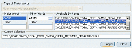
  • Do not modify the syntax directly in the Current Selection box of the PP Words Selection dialog box, or in the Resolved Syntax box of the Cycle Syntax Edition dialog box. Otherwise, the syntax on the machining operation is not updated with any modification you make to the PP Table syntax. Instead, modify the syntax of the machining operation by selecting a syntax from the Available Syntaxes list of the PP Words Selection dialog box.

For example, if your PP Table contains the following NC Instructions for Boring operations:

	/ 
							
	*START_NC_INSTRUCTION NC_BORING_1 
	*START_SEQUENCE 
	CYCLE/BORE,%MFG_TOTAL_DEPTH,%MFG_CLEAR_TIP 
	*END 
	*END 
	/ 
	*START_NC_INSTRUCTION NC_BORING_2 
	*START_SEQUENCE 
	CYCLE/BORE,%MFG_TOTAL_DEPTH,%MFG_CLEAR_TIP, 
	%MFG_BREAKTHROUGH 
	*END 
	*END 
	/ 
	*START_NC_INSTRUCTION NC_BORING_3 
	*START_SEQUENCE 
	CYCLE/BORE,%MFG_TOTAL_DEPTH,%MFG_PLUNGE_OFFST, 
	%MFG_CLEAR_TIP,%MFG_FEED_MACH,%MFG_FEED_RETRACT 
	*END 
	*END 
	/ 
	*START_NC_INSTRUCTION NC_BORING_4 
	*START_SEQUENCE  
	CYCLE/BORE,%MFG_TOTAL_DEPTH,%MFG_PLUNGE_OFFST,0, 
	%MFG_CMP_DWL_TIME,%MFG_CLEAR_TIP,%MFG_FEED_MACH, 
	%MFG_SPNDL_MACH,ON,0,0,%MFG_FEED_RETRACT  
	*END 
	*END

Then these syntaxes are displayed in the PP Words Selection dialog box that appears: