Creating a Plunge Milling Operation by Offset | |||||
|
| ||||
- Activate the Manufacturing Program and click Plunge Milling
 in the Prismatic Machining Operation action bar.
An Plunge Milling entity is added to the Manufacturing Program. The Plunge Milling dialog box opens at the Geometry tab
in the Prismatic Machining Operation action bar.
An Plunge Milling entity is added to the Manufacturing Program. The Plunge Milling dialog box opens at the Geometry tab .
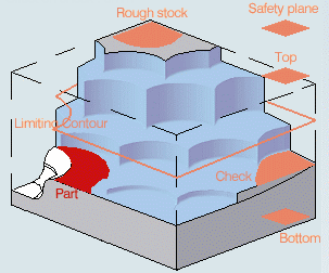
This tab includes a sensitive icon to
help you specify the
geometry.
Areas of the icon are colored red indicating that this
geometry is required.
.
This tab includes a sensitive icon to
help you specify the
geometry.
Areas of the icon are colored red indicating that this
geometry is required.
- Still in the Geometry
tab.
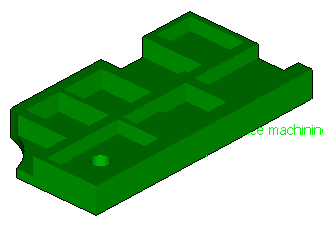
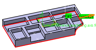
- Click the red area representing
the part in the
sensitive icon and select the part in the 3DEXPERIENCE platform.
Double-click anywhere in the 3DEXPERIENCE platform
to confirm your selection and redisplay the dialog box.
- Click the red area representing the stock in the sensitive icon and select the rough-stock in the PPR tree.
- Click the red area representing
the part in the
sensitive icon and select the part in the 3DEXPERIENCE platform.
Double-click anywhere in the 3DEXPERIENCE platform
to confirm your selection and redisplay the dialog box.
- Select the Strategy
tab
 .
.- Select By Offset as the Grid type.The dialog box changes:
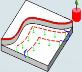
- Click the red curve in the sensitive icon and select a
contour in the 3DEXPERIENCE platform.
- Select By Offset as the Grid type.
- Go to the Tool tab
 to select a tool.
See Assigning a Tool Element to a Machining Operation
It is:
- a center cutting plunger
- a side plunging milling cutter
- Select the Feeds and Speeds
tab
 to specify the feedrates
and spindle speeds for the operation.
to specify the feedrates
and spindle speeds for the operation. - Go to the Macros tab
 to specify the desired transition paths.
 -
Click Display or
Simulate to check the validity of the operation.
See Displaying Tool Path.
- The tool path is computed.
- A progress indicator is displayed.
- You can cancel the tool path computation at any moment before 100% completion.
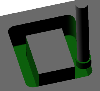
- Create a new plunging by offset operation, with the
following contour:

-
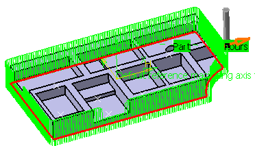
Click Display
The tool path is displayed.

-
Go to the Grid tab and increase Contour
Number to 6. Click Display.
The tool path is displayed.
 Note: If you play the Video from last save result, you see:
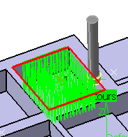
- Go to the Grid tab and decrease the Finished cutting
progress value to 1mm. Click Tool Path Replay and then
play the Video from last save result again.The results is: