About Robotic Polishing | ||||
|
| |||
There may be various types of polishing with conventional naming conventions, such as Grinding for deburring and rough finish of metal parts, Polishing for medium finish of manufactured items, and Buffing for smooth finish and mirror finish appearance of items.
The polishing wheel or belt may be either be part of a robot tool, or mounted on its own
machine in a fixed location with the workpiece being manipulated by the robot. 
In some cases, the robot tooling may be comprised of multiple polishing wheels which can be
individually raised and turned OFF or lowered and turned ON during the simulation. 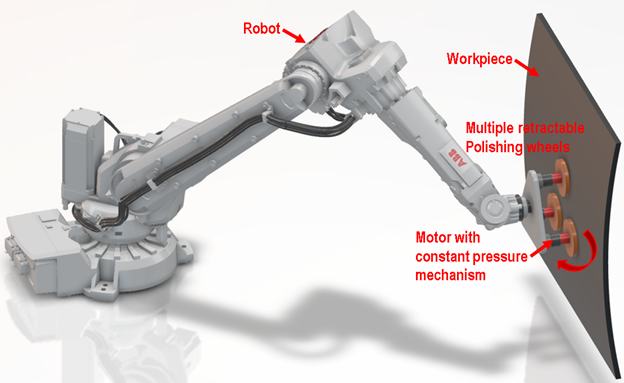
The desired result of the polishing for a given set of process parameters is quantified by the Abrasive Exposure. This is a percentage value which the solver computes at each mesh vertex point of the surface as the simulation progresses. 100% exposure corresponds to the ideal finish produced when using the Standard settings. This ideal exposure per surface mesh vertex point may be inferred by the values entered in the Calibration tab of the Blasting profile.
For example, a "standard polishing width" of 40 mm at a robot motion "standard polishing speed" of 100 mm/s implies that the ideal polishing time per surface point would be 0.4 seconds (40/100). Hence, this would be the default Polishing time value to enter in the first Polishing tab of the profile. You may also choose to increase or decrease this default value based on the specific requirements of their process. Variations during simulation with robot speed or grinding contact will result in the actual Exposure percentage computation and display. The finishing results may show some areas of the workpiece to be less than 100% and other areas to be at greater than 100%. Exposure much below 100 implies inadequate finishing while Exposure much above 100 implies excessive abrasion.
All other process parameters, such as belt or wheel speed, grinding force, etc. are assumed retained constant. In particular, the abrasive grinding force is automatically maintained at the required process value by the use of a constant pressure mechanism behind the wheel or belt. The fine positioning of the robot kinematic motions will affect grinding contact exposure but will not affect the quality of the finishing in terms of grinding force.
Note that unlike other spraying type technologies, the abrasion results for Polishing depend only on the time of contact between the simulated tool and each mesh vertex point of the simulated product. The Calibration tab page settings are meant to document the ideal behavior for a given tool and product usage combination as well as for potential OLP related purposes. They do not have an effect on the simulation abrasion result computations.
The ideal contact time per mesh vertex point is recommended by the calibration time parameters since the effective "width" of the polishing tool and the ideal process "speed" of the polishing robot motion together imply a duration of processing contact on the physical product surface as explained in the 0.4 seconds example above. Scenarios in the real physical system with different tool settings such as different tool rotation speeds etc would imply creation of different Polishing profiles with different calibration tab page settings.
The first Polishing tab page settings are the only ones used to compute abrasion results during a particular simulation run. You may modify the "ideal" settings implied by the calibration tab page parameters based on your experience and wish to adjust the simulation results.
Scenarios in the real physical system, where the tool is expected to be moved at different speeds to achieve desired polishing quality, would mean the creation of multiple "tools" that share the same calibration tab page settings but different simulation tab page settings. Note also that Contact tolerance is used in the occasional situation of simulation when sometimes the tool is almost in contact with the product, otherwise the tool is typically modeled with a slightly larger dimension that the physical tool to account for the spring loaded compensation behavior of the real physical system.
During simulation, the approach direction of the polishing tool relative to the surface being processed is specified by the positive Z direction of the coordinate system specified in the Direction tab page of the profile. This direction specification is required so that the effect of the polishing is applied to the correct side of the surface being processed. The position of this coordinate system should not be inside the polishing tool but rather behind the tool on the robot mount plate side, so as to provide the correct inference of the approach direction relative to the surface.