Polishing | |||
| |||
-
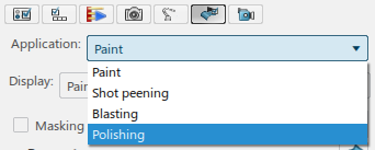
From the Surface section of the action bar,
click Polishing profile
 and
select a robot in the work area.
and
select a robot in the work area.
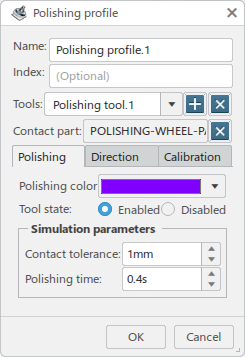
The Polishing profile dialog box appears.
-
You can enter a Name and specify an Index
for the new profile.

-
Select a polishing tool from the Tools list of available tools.
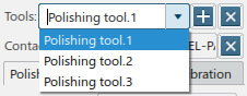
Click
 to add a polishing tool to the list, and
  to remove a tool from the list.
 -
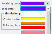
In the Polishing tab, click the Polishing
color list to select a color for the object.
-
Select Enabled in the Tool state section
for abrasion to occur on the polished surface. Select Disabled for
no abrasion.
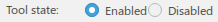
Note: Several tools can be associated to a robot. They can be activated or deactivated per profile. -
In the Simulation parameters section:
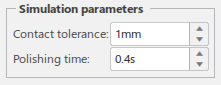
- Contact tolerance specifies the reference contact tolerance between the polishing wheel/belt and the product.
- Polishing time specifies the time at each surface point to produce the ideal 100% abrasion exposure during simulation.
-
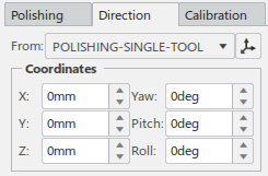
Click the Direction tab.
-
The current selection in the From list specifies the tool
profile from which the polishing part normal is relative to.
Click
 to further refine
the position.
to further refine
the position. 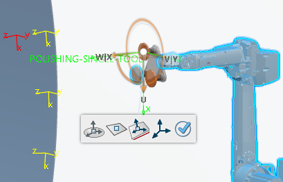
- The Coordinates section specifies the offsets for X, Y, Z, Yaw, Pitch, and Roll from the current TCP location.
-
The current selection in the From list specifies the tool
profile from which the polishing part normal is relative to.
-
Click the Calibration tab.
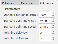
- Standard contact tolerance specifies the reference contact tolerance between the polishing wheel/belt and the product.
- Standard polishing width specifies the width of the reference polishing wheel/belt.
- Standard polishing speed specifies the reference robot TCP speed that will result in 100% abrasion exposure.
- Polishing delay ON specifies the time delay in spray deposition turning on after shot flow is turned on.
- Polishing delay OFF specifies the time delay in spray depostion turning off after shot flow is turned off.
-
Click OK to create the new Polishing profile.
The new profile appears in the Profiles side tab:
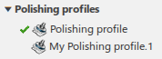
The profile can be edited by double-clicking the thumbnail in the Profiles side tab.
-
From the Surface section of the action bar, click Surface
Trajctory
 and create one
or more surface trajectories as described in Generating Paths.
and create one
or more surface trajectories as described in Generating Paths.

-
From the Surface section of the action bar, click Generate Robot
Task
 and create a task as described in Generating Surface Tasks.
Note: In the Trigger Parameters section of the Create Operations dialog box, select the polishing profile created above from the App. Profile list.
and create a task as described in Generating Surface Tasks.
Note: In the Trigger Parameters section of the Create Operations dialog box, select the polishing profile created above from the App. Profile list.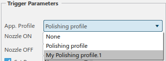
-
Set the Paint Results tab of Simulation
Options for Polishing.