- Click New Interference
 .
.The New Interference dialog box appears.
- If desired, in the Specifications tab, select the Clearance check box, and enter a Clearance Value.
Clash and contact is selected by default.
- In the Context tab, click Add New Group.
The
Tools Palette toolbar appears,

as does the
Group
Definition dialog box.
- On the geometry or in the tree, select the products for Group 1, and click OK in the Group Definition dialog box. Use the Tools Palette for assistance as necessary.
Group 1 is created.
- Repeat the previous two steps to define Group 2 and select Groups against Groups.
- Click Feedback.
The Feedback tab appears.
- Select Clash, contact or clearance, Display interferences list, and click OK.
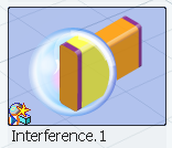
Once the options are selected, an interference thumbnail appears.

To use this probe, , and
.
- If you save the content in your manufacturing scenario, the state of the probe in the scenario
in which it is referenced can persist from one 3D Simulation session to another.
- If you selected Display interferences list when you
created the probe, you can right-click the thumbnail in the Results
 panel and select Interference
Analysis.
Note:
For more information on the commands available when you
right-click the probe, see Probe Commands.
 panel and select Interference
Analysis.
