Compute Rework Areas
You must first compute the rework areas.
-
From the
Surface Machining section of the action bar,
click Rework Area
 . .
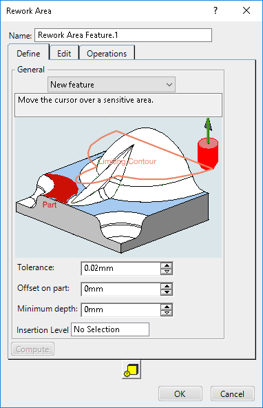
The Rework Area dialog box opens at the
Geometry
tab
 .
-
Still in the Geometry
tab:
-
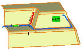
Click the red area in the sensitive icon and select the part in the work area.
-
Double-click anywhere in the work area to confirm your selection and redisplay the dialog box.
-
Change the Entry diameter, e.g. to 10 mm, the
Corner radius, e.g. to 5 mm and the name to
Rework.
-
Click Compute.
- A progress indicator is displayed. You can cancel the tool path computation at any
moment before 100% completion.
- The rework area is created and can be seen in the Machining
feature view.
-
Click Load from at the top of the
dialog box and select a machining operation, a tool or a machining area in the Manufacturing View.
- Load From loads all the appropriate data from an existing
machining operation, a tool or a machining area. It is only an accelerator to define the parameters
of the rework area. It may be necessary to tune up some of those parameters to
obtain a correct result.
- The machining geometry referenced in the machining operation cannot be edited nor deleted within the machining operation.
- When the selected machining operation has its geometry as Design on Part Operation Level, a
warning is displayed and the Load From fails.
-
In the Define
tab:
- Either click the red area of the sensitive icon and select the part in the work area. Double-click anywhere in the work area
to confirm your selection and revert to the dialog box, or
- Use the Face Wizard to select the faces to create the area
to machine.
-
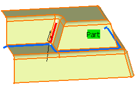
Define the limit line in order to restrict the area to be reworked.
-
Select the tool axis that you used to machine the rest of the part.
-
Enter the tool data that you used to machine the rest of the part:
-
To use a conical tool, type a positive cutting angle. For an end mill tool, leave
the default value of 0 degrees.
-
Enter the machining
Tolerance for the rework area. For the sake of speed, use
the same value as for the machining tolerance in the machining operation that the rework area is going to be used in.
-
Optional: Use a smaller tolerance in the machining area and a larger
one in the machining operationmachining operations, reducing the machining operation one until you obtain satisfactory results as regards the finish that you
require.
-
Enter
the Overlap, that is the distance that you allow the tool to
go beyond the boundaries of the rework area. It is defined as a percentage of the
tool radius.
-
Enter the Offset on part, that is
the offset that is computed for the rework area with respect to the part.
-
Enter the Minimum depth, that
filters out areas to ignore because they are not deep enough.
-
If required, select the Contact with
check check box to detect bitangency areas between part and check
elements.
At least one contact point of tool with the Part element is required.
-
Click Compute.
Computing Rework Areas from IS
You can compute the rework area from intermediate stock (IS).
-
To use the intermediate stock functionality, define the stock in the Part
operation dialog box.
The rework area uses the stock.  -
Double-click a Part Operation in the Activities Process Tree and activate the Activate the intermediate stock option under
the Intermediate Stock section of the
Option
 tab in the
Part Operation dialog box. tab in the
Part Operation dialog box.
-
In the Surface Machining section of the action bar,
click Rework Area from IS
 . .
-
In the Rework Area dialog box that appears, open the
Define tab and specify the parameters of the rework area.
The Define tab allows you to select the part or a set of
faces, a limit line (to restrict the rework area), and the tool axis. With this tab,
you can do the following:
- Use the menu to select a machining feature, when available.
- Select a part body element in the 3D area
to select, or right-click the element for additional methods.
- Specify the Tolerance.
- Specify the Offset on part, which is the offset that is
computed for the rework area with respect to the part.
- Specify the Minimum depth for the intermediate stock to
filter out values below this minimum.
- Specify the Insertion Level to specify the location for
inserting operations.
-
Click Compute and select an item in the Activities Process Tree.
For the computation of the rework area, the input stock is the output stock at
this level, or the first valid output stock before this level.
-
Click Update Input Stock
 to
update the input stock of the current operation. Click the icon once to display the
input stock and double-click to hide the input stock. to
update the input stock of the current operation. Click the icon once to display the
input stock and double-click to hide the input stock.
The input stock computes and takes into account all the previous
operations. Note:
If you have not defined a stock, the following icons are
displayed: Stock is not valid. Compute and OK are
disabled.
Stock is not valid. Compute and OK are
disabled.
 Intermediate stock is not updated for this insertion point.
Compute and OK are disabled. You can
update the intermediate stock by clicking the icon. Intermediate stock is not updated for this insertion point.
Compute and OK are disabled. You can
update the intermediate stock by clicking the icon.
When you define the
insertion point, the status of the icon is updated.
-
Open the Define tab to transform the set of computed rework
areas.
-
Right-click an item in the Subsets list to edit the
subset.
When you right-click a subset, you can do the following:
- Hide/Show.
- Delete.
- Copy contours from another subset.
- Move contours from another subset.
- Merge contours.
- Smooth a contour.
-
Edit the subset with the options in the dialog box.
-
Open the Operations tab to assign operations to rework
areas.
You can use this tab to do the following:
- Use contour driven (parallel contour only), spiral milling, Zlevel, sweeping
finishing, and advanced finishing rework areas.
- Link operations and subsets from rework area computation and edition.
- Define an overlap between rework areas. Overlap is the same for all
operations.
- Assign operations.
-
Click OK to save.
The operations appear in the Activities Process Tree under the defined insert level and the rework area appears in the Manufacturing View. Note:
When you modify previous operations or intermediate stocks, the rework area
is not up-to-date in the Manufacturing View as well as the operations assigned to the rework area in the Activities Process Tree.
-
Optional: Create a parallel contour guiding strategy by selecting the
Parallel contour
Guiding Strategy option.
Edit Rework Areas
If you find that there are too many areas to be reworked or if you decide to
concentrate on only a part of the rework area, you can go to the Edit
tab and
define other parameters to restrict the area to rework by creating subsets.
Note:
The graphic properties of the visualization lines of rework areas are not editable.
-
Use the
filters proposed in Divide by.
By default, an
Angle and a Length filter are
proposed.
-
Optional: Activate a Width filter.
Subsets are split using the Angle criterion.
Splitting is carried out only if the length of the resulting subset is greater than
the Length value.
By default, this Length is set to 6 mm.
Note:
For an optimum result, we recommend that you set the Length
value to 1/3 of the tool diameter.
-
Click
 to compute or update the subsets. to compute or update the subsets.
The list of subsets is displayed in the dialog box, with the criterion used
for its computation, its display dolor and the number of elements in the subset. The
column Operation indicates whether a machining operation is assigned to the subset. Note:
A machining operation is effectively assigned to a subset when an Insertion Level has been defined in
Operations
tab!
-
However, creating subsets with the above criteria may not be sufficient. In that
case, split the subsets manually, by points.
-
Select one subset in the list.
-
Select Divide by Points in its context menu or click
 . .
A red dot appears on the selected subset. 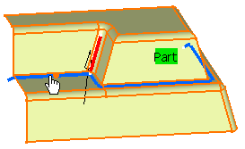
-
Move the pointer along this line, to the required place.
-
Click the line to create the splitting point.
The red dot is replaced by a white cross, the subset is split, and the number
of elements is updated in the list. Create as many splitting points as
required.
-
Transfer an element from one subset to another:
-
Select in the list the subset to which you want to add an element,
-
Choose Add/Remove from its context menu or click
 , ,
-
Select the element you want to remove from the other subset.
-
Click
 to create an new empty subset, then use the
Add/Remove menu to fill it. to create an new empty subset, then use the
Add/Remove menu to fill it.
-
Click
 to remove unwanted cutting points. to remove unwanted cutting points.
-
Click
 to delete no-updated subsets and selections. to delete no-updated subsets and selections.
Assign Operations
You can assign a machining operation to a rework area in the Operations
tab.
-
Place the pointer in the Insertion Level box and click in the
Activities Process Tree to define where the machining operation is to be inserted.
- The box is updated and the red arrow disappears while the Assign
Operation parameters are displayed.
- All the tools used in existing machining operations are available from the Tool Reference list.
- The Reference Tool applies to all the machining operations to create.
-
Select one subset to which you want to assign a machining operation and define the machining operation parameter under Assign Operation that is now available.
-
Still under Assign Operation:
-
Select one type of machining operation from the Assign list.
-
Set the Stepover value.
-
Click the tool icon to define its axis.
The list of subsets/operations is updated accordingly. To revert to an automatic step
over, click Auto. The value is replaced with the label
Auto. Note:
- Use the same size of tool in a pencil operation as that defined in the rework area
in order to reduce computation time. You can also use a larger tool with pencil
operations.
- If you choose to use a tool that is smaller than the one defined in the rework area,
consider the rework area to be simply a set of limiting contours and use a
contour-driven operation.
- If you use a smaller tool with a pencil operation, no tool path will be generated
for the rework area.
Remove a Rework Area
You can delete rework areas from the Manufacturing View.
Use the Remove Result
context menu to remove a rework area feature from the Manufacturing View.
A message confirms the removal of the feature.
|
