- From the Surface Machining section of the action bar, click Geometrical Zone
 . . - In the Geometrical Zone dialog box that opens:
- Press Line
 , , - Enter a Name for the contour you are going to create, e.g. MyContour,
and click the orange outline in the sensitive icon.
- Using the Edge Wizard, create a contour on the part:
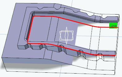
Click OK to validate and exit the dialog box.
- Create a Sweeping Operation:
- Select the
whole body for the part.
- Choose Select zones in the limiting contour
context menu.
- In the Zones Selection dialog box that appears, select MyContour under Not selected and click the arrow to send it to Selected.
- Click OK in the Zones Selection dialog box.
-
Click Display or
Simulate.
The geometrical zone limited by MyContour is machined. 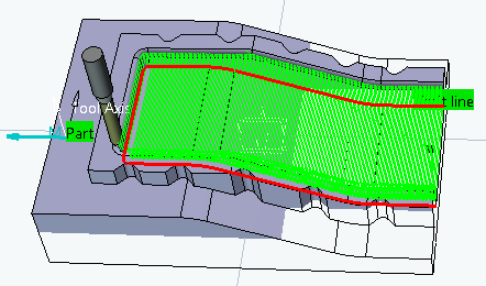
- You can also define geometrical zones in a machining operation
dialog box:
- In the Geometry tab, click Check
- Using the Edge Wizard, select a face.
- In the Geometry tab, right-click Check and select Export in its context menu.
- In the Export dialog box that opens, enter a Name, e.g. MyPlane, for the plane you are creating and validate.
- In the Check context menu, choose Select zones.
MyPlane is already found under Selected.
|