Validating Reachability with the Analysis Disc | |||||
|
| ||||
-
From the Trajectory Editor, click Validate Reachability
of Tags
 and select a tag in the trajectory.
The robot snaps to the selected target, and the Analysis Disc appears.
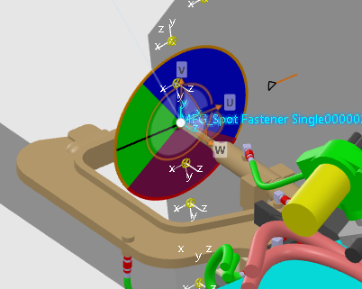
The Analysis Disc Details dialog box also appears.
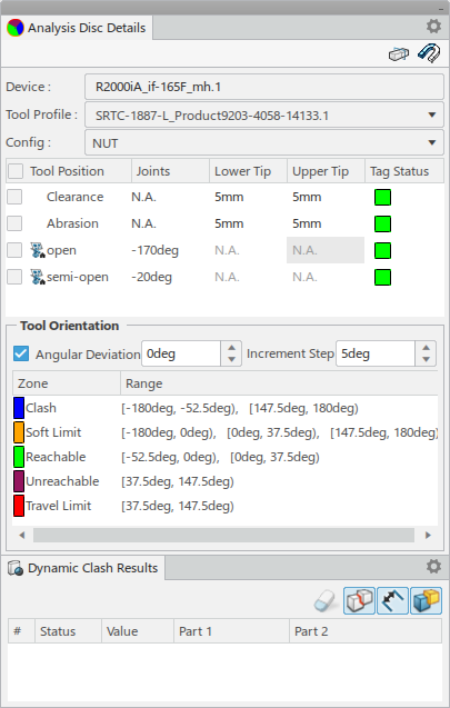
- Device indicates the selected robot.
- Tool Profile indicates the current profile for the selected
device. You can select a different profile from the list of defined profiles.

- Config indicates the current configuration. You can select a
different configuration from the list of defined configurations.

-
Select Tool Position to select or clear all tool home positons
and Clearance and Abrasion conditions listed
in the table. Specific tool positions and conditions can also be selected individually.
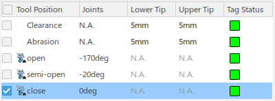
The Tag Status column provides feedback on the reach and clash status for each tool home position, as well as clearance and abrasion conditions.
Click Show Preferences
 to view the
Reach Legend.
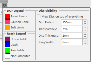
- Reach Legend indicates the colors that represent
Unreachable, Clash,
Reachable, and Not Computed
reachability status. Note: These colors are defined in the Analysis Disc tab of Me > Preferences > Simulation > Digital Manufacturing Apps Common Services > Manufacturing Apps Common Services.
- DOF Legend indicates the colors that appear on the disc that
represent Travel Limits, Caution Zone,
and Soft Limits.Note: These colors are defined in the Device Analysis tab of Me > Preferences > Simulation > Digital Manufacturing Apps Common Services > Manufacturing Apps Common Services.
- Disc Visibility allows you to make local changes to the Disc Visibility preferences defined in the Analysis Disc preferences tab. Any changes made in this panel are valid for the current 3DEXPERIENCE session, and do not affect the settings stored in the Analysis Disc preferences tab.
Upon selecting a home position or condition in the Tool Position table, the Analysis disc is displayed for that position. When multiple selections are made, the Analysis Disc for all selected positions is displayed.
Selecting a row in the Tool Position table moves the tool to the selected position.
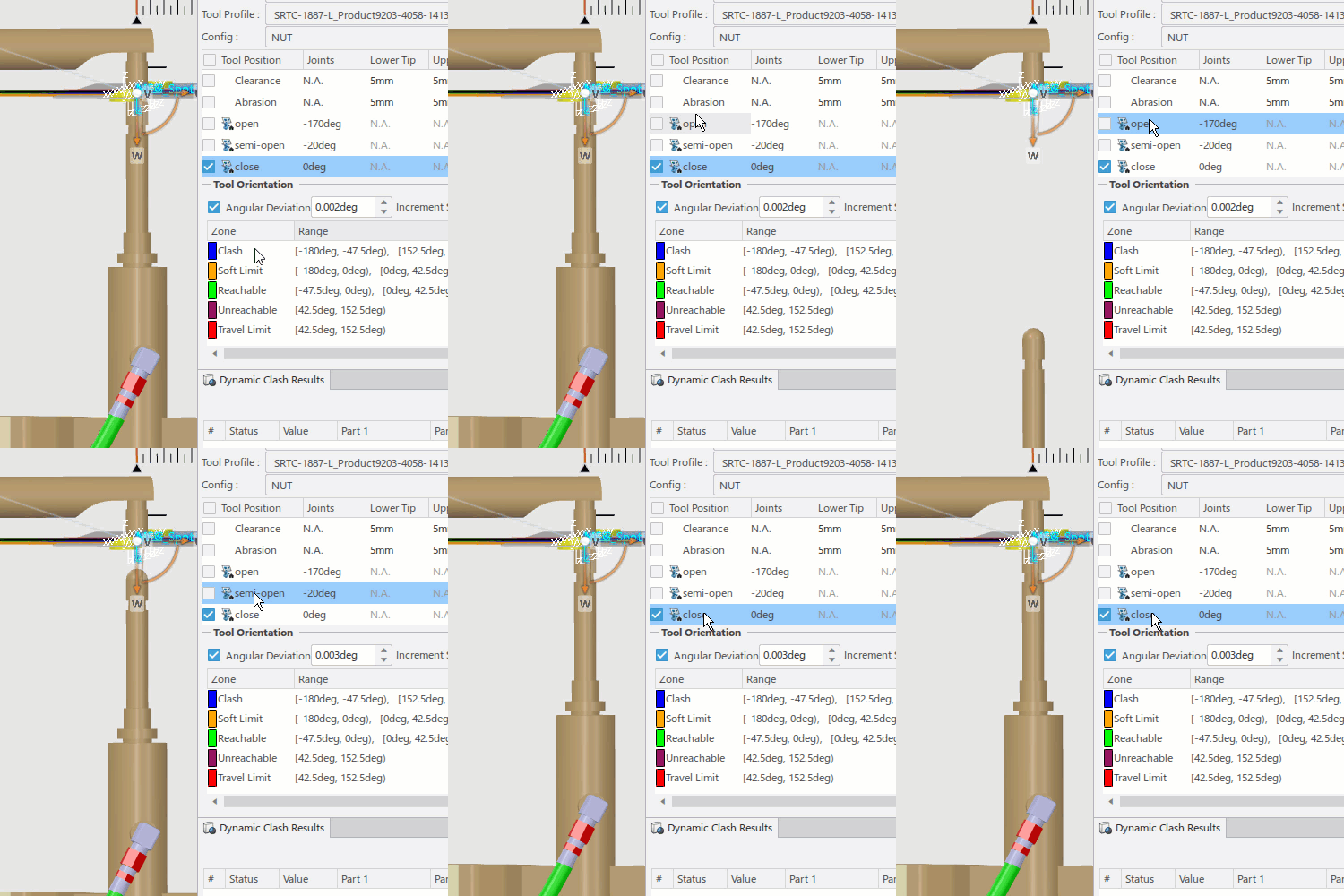
- Tool home positions are indicated with
 .
. - Values displayed for Clearance and Abrasion Lower Tip and Upper Tip are defined in the Analysis Disc tab of Me > Preferences > Simulation > Digital Manufacturing Apps Common Services > Manufacturing Apps Common Services.
- Reach Legend indicates the colors that represent
Unreachable, Clash,
Reachable, and Not Computed
reachability status.
-
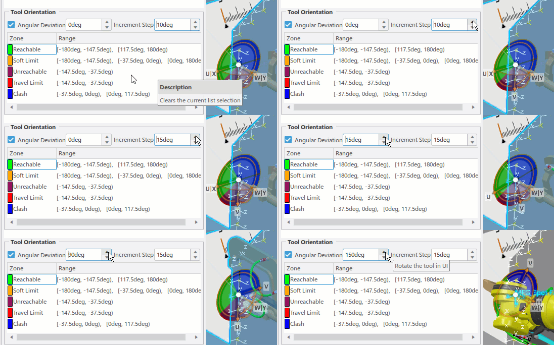
The Tool Orientation section allows you to precisely orient the
tool, and provides sector details for each color-coded zone on the Analysis Disc.
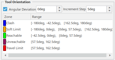
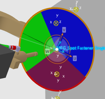
Reachable and unreachable zones are indicated by color on the face of the disc, while the travel limits of the robot are indicated as a ring around the disc.
The Travel Limits ring around the disc features a reference marker that denotes the original position when the tool initially snaps to a location.
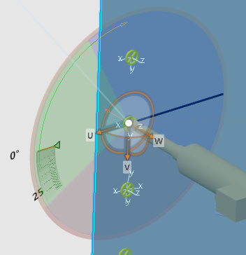
As the tool is manipulated around the target, the Angular Deviation value is continuously updated to reflect the current angle between the black reference line on the disc (indicating the current tool position) and the reference marker. Zones listed in the Tool Orientation section are calculated in reference to the reference marker.
You can select Angular Deviation and define an Increment Step value to move the tool around the target by a specific amount using the Angular Deviation up and down arrows.
-
The Dynamic Clash Results panel provides feedback on object
clashes when moving the tool around a given target.
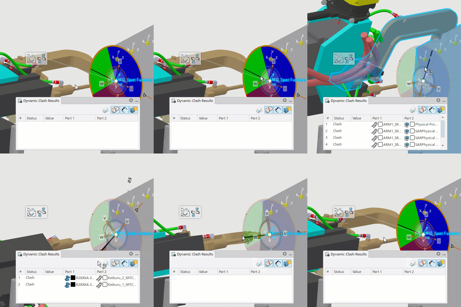
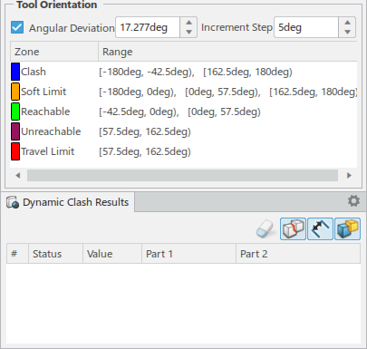
You can click
 to snap the
Dynamic Clash Results panel to the Analysis Disc
Details dialog box.
-
Use the compass to move the Analysis Disc around the target to a reachable (green) area
of the disc.
Once the required location is found, click Modify Tag Position
 in the context toolbar to orient the tag to the current compass position and orientation.
When analyzing a target, you can also click Flip Tool
 in the context toolbar to flip the tool at the current compass location along the approach direction. The
analysis disc is updated to provide results with the flipped tool position for the current
compass position. The Tag Status for each tool position becomes green to indicate the new reachable state.
-
Repeat the above steps for each tag that requires reachability analysis, and click
Validate Reachability of Tags
 to close the command when finished.