3D Simulation Panel Contents

The 3D Simulation environment is organized by panels; each panel represents a kind of content. This section gives you an overview of the kinds of information in the specific panels.

This page discusses:

Default View of Panels

You can use panels to concentrate on logical subsets of your work.

Most of the panels are available in all apps with a 3D Simulation environment; in some cases, panels are only available in specific apps.

The common panels:

Sequencing
ASO
Scenarios
Simulation States
Excitations
Probes
Results
Behavior
Tree

Sequencing

The Sequencing panel provides a simple way to program resources such as robots, humans (manikins), or tool devices and synchronize them at the organizational level.

The resource program is defined by a task.

  • A task is composed of instructions such as robot and human activities.
  • Control flow statements (such as loops, conditions, or tasks calls) allow you to order the different activities.
  • You can also use defined variables, constants, output, and input parameters called IOs. You can define them in a task or at the resource level.

See About the Sequencing Editor.

ASO

The ASO panel shows which object is the active simulation object (ASO), and provides tools to select a different object.

Any work you do in the panels is done to the ASO. When you open 3D Simulation, the object you have selected immediately before opening 3D Simulation determines what your initial ASO is. You can use commands in the panel to select another ASO:

  • Click Up to select an ASO above the current one in the product or resource tree.
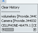
  • If you have selected other ASOs in this session, click History and select one of the ASOs in the list.

  • To go back to the ASO you used immediately before the current one, you can click Previous .
  • From that ASO, click Next to return.

You can also select a different ASO using a dedicated command within the App Options panel and a selection assistant. See Selecting the Active Simulation Object.

Scenarios

A scenario comprises excitations, either singly or in a sequence, as well as behaviors, probes, states, and simulation logic.

This documentation describes how to create a general manufacturing scenario. Other kinds of scenarios are part of a specific application, such as Process Flow Simulation.

Simulation States

A state is a snapshot of the position and simulation properties of objects at the point where the state is created. You can include states in scenarios.

When you create a new simulation state, it contains only the state (that is, entities such as positions) of the current ASO and its children. Create the state at the highest level in the resource hierarchy that contains all the resources for which you need to save positions.

Note: Siblings or parents of the ASO are not considered when creating a new simulation state.

In 3D Simulation, you can apply a simulation state at any time by selecting the required state's thumbnail from under the Simulation States panel, and clicking Apply State.

During a simulation, the active simulation state, if any, is applied at the beginning of the simulation when you simulate:

  • A sequence (or a scenario containing a sequence) using the Compass Play command
  • A resource behavior.

The simulation state is not applied when you simulate a scenario that contains only tracks, that is, no sequences.

Excitations

The excitations are actions involving parts or resources. You can list these actions in a sequence or add them singly to scenarios. Some of the excitations (for example, tracks) exist in specific apps (for example, Assembly Evaluation), and are described in those app's user guides.

Although assembly sequences can be created under Excitations , sequence objects created under the Behavior node of a resource through Sequencing are not displayed in Excitations . Instead they are displayed in Sequencing , and obey the rules for showing objects in Sequencing. For example, the correct ASO must be defined.

Probes

Probes are items that collect data (such as measurements) or do data analysis (such as clash analysis). In 3D Simulation, you create a probe thumbnail in the Probes panel. In most cases, probe specifications persist from one session to another.

Probes display all probes available. However, for the current scenario, there could be a subset of referenced probes. When you change the current scenario, the probes' status changes accordingly, to reflect the probes referenced by the new current scenario.

The current scenario's referenced probes are clearly marked in the panels: their thumbnails have an icon in the upper corner; the unreferenced probes have no icons. The icons for the referenced interference probes signify whether the clash detection results in the clash being highlighted or in the simulation being interrupted.

The information a probe provides only appears in the 3D area when the probe is part of the scenario. For example, if you create a measure probe, you only see the measurement once the probe is assigned to the current scenario.

In most apps that use 3D Simulation, a dynamic clash probe is available by default. Dynamic clash detection is performed between the moving parts against the rest of the entities in the viewer. It differs from static clash or interference checks, which are performed between predefined groups, whether the parts move or not.

Note: Probes are only applied to the current window. It is not guaranteed that the probes are updated in other windows that share the same content.

See Activating the Dynamic Clash Probe and Defining an Interference Probe.
Results

Results are created by other objects in the session (for example, scenarios, by running the Simulate and Generate Results command). Animation or movie thumbnails appear in the Results panel.

Results persist from session to session and some results can be exported.

Behavior

Behaviors are sequenced or parallel actions that are associated with resources.

In most cases, the behaviors you can create within3D Simulation are described in the user guides for the apps from which they originate.

Tree

The tree is not featured in the3D Simulation environment, although you can view it at any time.

When you first access the tree within a session, you can either:

  • Right-click work area, and select Display > Tree Display.
  • Press F3.

Once you have accessed the tree, a new panel for the tree is added. This panel cannot be undocked.