-
To filter and merge a product like this one:
-
From the
IP Protection section of the
action bar,
click
Product Filtering & Merging
 . .
-
Select the product node.
This product can be:
- A product with a non-shareable representation
- A product with a shareable representation
- A 3D Part.
-
Enter an identification string on the right of the product name.
-
Click the arrow to expand the dialog box.
-
Define the creation mode of the final product.
- With
Create: A 3D Part, the input product is
filtered and merged into one 3D Part, that is a product with an aggregated
representation.

- With
Create: A product with a shareable
representation, the input product is filtered and merged into one
product containing one shareable representation.
- With
Create: A product with non shareable
representation, the input product is filtered and merged into one
product containing one non-shareable representation.

-
Optional: Select the
Merge body check box.
- For solids:
- The solids found in all the bodies of each representation of the
original product are merged in one body (Boolean operations).
- For surfacic elements:
- The ordered geometrical sets are merged in one hybrid body, if
you have enabled hybrid design.
- The geometrical sets are merged in one body, if you have not
enabled hybrid design.
Note:
3D Tolerancing & Annotation
data are not kept when this option is selected.
-
Optional: Under
Keep, select the
Colors check box, then the required option.
Note:
Graphic attributes other than color and transparency (line
type, thickness, symbol, ...) are copied with their default value regardless of
the status of this option.
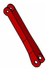
- Overloaded faces: This option
overrides the standard behavior for colors, transparency and applicative
attributes, and keeps the visual aspect of the original data. For example, if
the color of one face has been changed like this
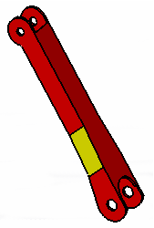
the result of the transfer looks the same.
Notes:
- Be aware that this option may be time consuming.
- If a body is not up-to-date (update mask displayed in the
tree),
the color of the subelements will not be kept, even if this option is selected.
- When the color or the opacity of a subelement has been
overloaded (at the level of the subelement or at the level of one of its
parents), in the result part, the overloaded color or opacity is kept on the
subelement, but can be changed at the level of the subelement only, not at that
of its parents. If you overload the color or opacity of one of its parents, the
color or opacity of the subelement will not change.
- Container: The whole transferred solid
takes the color and transparency of the original body.
- When
Colors is not selected, the result takes the
default color and transparency.
-
Optional: Select the
Keep annotations check box to transfer
3D Tolerancing & Annotation
data (FTA) and 3D Tags from
Generative Shape Design
found in the shape representation of the product to filter.
-
Optional: Select the
Contains the string check box to restrict
the filtering process to
3D Tolerancing & Annotation
captures with a name containing a string you provide.
- If you leave the string empty or undefined, all the
3D Tolerancing & Annotation
features are transferred.
- The names of the Geometrical Links features of the
transferred
3D Tolerancing & Annotation
features (that are displayed in the
Connection Management dialog box) are
partially kept:
- The names of
Group Of Surfaces and
User Surface features are kept.
- The names of
Geometric Component features are
not kept, and are replaced by a default name in the result product.
- In addition, the transferred
3D Tolerancing & Annotation
features are displayed in the
tree
with the same names as in the original product and in the exact same order.
- You will be asked to propagate the original product after
having filtered is using the
Keep annotations. Do not propagate the
product, unless you have made modifications.
See
About the Filtering of 3D Tolerancing & Annotation
for more information.
-
Optional: Select the
Material check box to transfer the material
information.
Material applied to faces is not taken into account.
- If
Merge body is not selected, only material
applied at the body level is taken into consideration and kept. If in the
origin product material was applied to a 3D Part or 3D Shape, but not to
bodies, the material is not kept.
- If
Merge body is selected, material is kept
only if merged bodies have the same material.
-
Optional: Under
For sketch, select the
Specifications of sketches check box.
- When this option is not selected, the sketch is transferred
As Result. The resulting sketch is not
editable.
- When this option is selected, the sketch is transferred
As specified in Part document:
- The resulting sketch is editable.
- The sketch support positioning is switched to isolated
definition mode.
- The sketch parameterization and all its associativity with
external features is removed:
- Constraints and their formulas
- Output and output profile features
- All construction geometries
- All geometries in NoShow.
- Use-edges (projections, intersection, ...) are isolated and
converted to sketched curves.
- In the case of used-edges with a complex curve mark, the
wire isolation cannot keep the sub-element naming, nor the previous orientation
of the curves.
-
Optional: Select a Visualization Filtering
option.
|