Splitting the geometry involves switching to the Structure View and activating the Extract command . You can split a representation to access underlying triangle meshes.
You must switch to structure view to
edit the product structure.
A
3D Design-Structure View switch is available in the
Data Preparation action bar.
To access the context toolbar of
interest, click
Structure
View.
The structure
view is activated.
To switch back to the
3D Design view, click
Structure view.
Extract 3D Representations
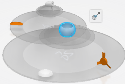
You can extract geometry elements to group them into a separate 3D representation.
In the Structure View, select one or more subrepresentation elements in the product structure to extract.
Important:
The selected geometrical elements must share a common parent representation in the product structure.
The Extract command appears in the context toolbar.
Click Extract.
A new product and a new representation below that product are created. The representation contains the geometrical elements selected for the extraction. These geometrical elements are removed from the original representation.
Note:
The created prepared product
is applied the same design range as its direct parent product. For more
information, see
Experience Models Preparation.
Extraction Example
Let's consider the following product structure:A product with two 3D representations containing geometrical sets underneath.
If you extract geometrical sets (indicated as three light blue elements in the left figure), a new "leaf" is created in the prepared model containing a product, a 3D representation and the extracted geometrical data set (the prepared model is shown in a blue circle in the right figure).
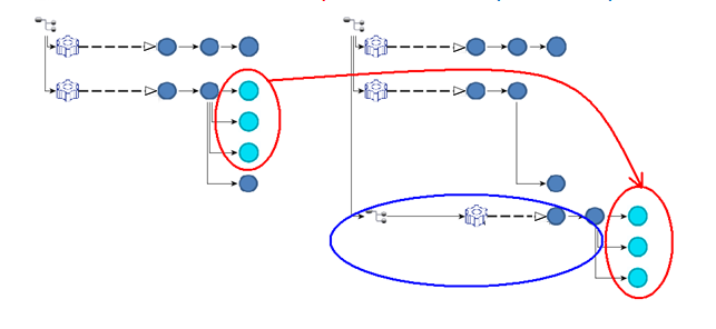
Important:
During the extract operation, a new part is created. The design range of the new part is the design range of the product directly above the part containing geometry to extract.