-
From the Sketch section of the action bar,
click
Profile Feature
 . .
The Profile Definition dialog box
appears. The name of the profile you are creating is displayed in the
Name box.
-
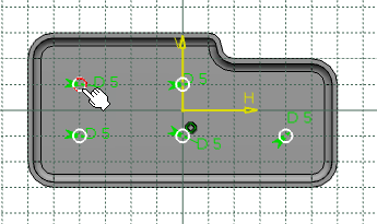
Select the required 2D elements.
The geometry you selected is displayed in the
Input Geometry table, the resulting geometry,
that is all geometrical elements that eventually are exposed in the work area, in the Output Geometry table.
- Optional:
Under Check, select the required check boxes to validate
the profile definition.
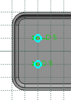
If the selected elements are not connected, a warning message is displayed in
the dialog box detecting an ambiguity you need to solve: the two selected
circles are not connected and the Check connexity
check box is selected.
-
From the Color palette, assign the color to the profile
feature.
-
Click
OK to confirm the creation.
The parameters and options you defined for this profile are kept
as default values for the next profile you will create later on.
The output feature is displayed as
Profile.x in the Outputs node in the tree.
-
Create 3D features using
Part Design
or
Generative Shape Design.
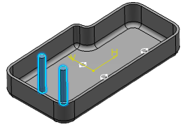
The profile does not appear under the created 3D feature.
|