- In Electrical Systems Design, link logical equipments to
a space.
For more information, see Electrical Systems Design: Creating Space Links. In our example, a logical equipment is linked to the highlighted space. 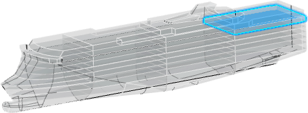 -
Open the logical and physical data:
-
From the
Search Results panel, right-click the logical or
the physical root and select
.
For more information, see System Finder User's Guide: Exploring RFLP Structures.
Both logical and physical roots are explored in System
Finder.
-
In the tree, select both roots and select
Open in the context menu.
-
Activate the physical root product in Generative Electrical 3D
Design.
-
From the
Generative Electrical 3D Design section of the action
bar, click
Logical to Physical
 . .
The
Logical to Physical Synchronization Manager dialog box appears. -
In the tree, select the logical system containing your logical equipments, and then click Analyze.
In the Element column, the physical equipments to be placed appear.
Under Modification Information, a warning indicates that their aggregating physical product is unknown.
-
Select the physical product in which to place the physical equipments:
- Right-click the physical equipments and select Set Father.
- In the tree, select your physical root.
Under Modification Information, a message indicates that the physical equipments are ready to be placed.
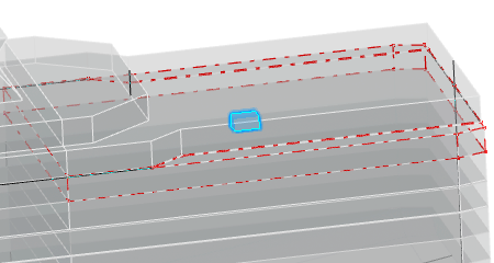
- Click Synchronize, and then click Close.
- In the 3D area, the physical equipments are placed in the center of gravity of the space linked to the logical equipments.
- In the tree, under the Implement Relations node, the implement links created after the synchronization appear.
|