Generating a Configured Harness | |||
| |||
-
Select one or several conductors (Conductor1 in our
example) in the original harness in the tree.
You can also select the root product, electrical physical system, electrical geometry, electrical branch geometry, a device, equipment, branch or segment. Then, you can select one or several conductors in the Harness Configuration panel (see next step).

-
From the Import/Export section of the action bar, click Harness
Configuration
 .
The Harness Configuration panel appears displaying the selected conductor, Conductor01.Note: If you have selected several conductors, you can:
.
The Harness Configuration panel appears displaying the selected conductor, Conductor01.Note: If you have selected several conductors, you can:- Filter the conductors' specifications in the column header when they are
configuration criteria:
- Evolution Effectivity
- Harness List
- Variant Effectivity
- Route status
- From end
- To end
- Electrical system
- Separation code
- External diameter
- Bend radius
The filter symbol changes from
 to
to  when the filter is activated in the column.
 You can add the customized columns using the business rules. For more information, see Compute Additional Attributes Values of Routables for Harness Configuration (EWR_ComputeAdditionalAttributesValuesOfRoutablesForHarnessConfiguration) and Compute Additional Attributes of Routables for Harness Configuration (EWR_ComputeAdditionalAttributesOfRoutablesForHarnessConfiguration).
- Manage the visibility and order of the columns by right-clicking any column header.
- Filter the conductors' specifications in the column header when they are
configuration criteria:
-
Click the conductor's name.
Notes:
- All the conductors and conductor groups under the selected occurrence will be selected.
- Conductors that are not routed or conductors having invalid route are not displayed in the Harness Configuration panel.
- If a child conductor or conductor group inside the conductor group is selected, its entire parent conductor group will be selected as well.
- If you select a conductor group, its child structure and the child structure of its linked conductor group specs should be similar.
-
After selecting the conductor, click Harness
Configuration
 in the Harness Configuration panel.
The name of the preconfigured harness and the number of wires on it are displayed in columns added to right side of the Harness Configuration panel. You can then select the conductors and then the Harness Configuration
 to add another preconfigured harness.
Tip: To rename the preconfigured harness, right-click the its name and select Edit Name. - Optional: To remove the preconfigured harness, select the preconfigured harness name and then click Remove.
- Optional: To highlight the conductors on the preconfigured harness in the Harness Configuration panel and in the 3D area, click Preferences on the top-right corner of the panel and select the Highlight conductors check box.
-
On the right side of the Harness Configuration panel,
click Generate Preconfigured Harness
 to generate all the configured harnesses.
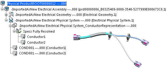
Next to the original harness window, a new product opens, containing the configured harness. It contains only the selected conductor and its geometry (under the Branch set). New references are created for the root product, electrical geometries, electrical physical system, electrical branch geometries and any intermediate product in the product structure.

Notes:- If there are several preconfigured harnesses, they are opened in separate tabs.
- In the generated harness, you find all the elements that are
connected to the selected conductor in the original harness, such
as:
- Device
- Support
- Branches with conductors
- Conductor lengths can be kept only for branches built with the Length mode. For the other build modes, the conductors' length may be different in the configured harness.
- Segment (and segment length). The diameters of the remaining
branch segments are re-computed according to the value set
in the Diameter and bend radius to its content option
in
Me
 > Preferences > App Preferences > 3D Modeling
> Electrical and Electronic
Systems > Electrical 3D Design > Conductor.
 - Protection. A protection shared by the kept segment and the removed segment is resized to fit the kept segment.
- The geometrical definition of the branch route corresponding to the remaining segments is not changed in the configured harness.
- Here is the list of the objects that are not re-created in the
configured harness:
- Electrical devices that are not connected to conductors
- Empty segments (generated by the removal of conductors in the configured harness) and their protections.
- Supports or mechanical parts that are not connected to the branch. For 3D Parts, 3D Shapes, conductors, connectors and supports, the same reference will be used in the configured harness.
- Distant link between two branch geometries (internal distant links are kept).
- No links are created between the original and the configured harnesses.
If you had selected Conductor02 in step 3, you would obtain:

- Save the configured harness.