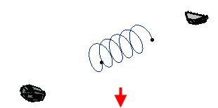
- Double-click to activate the electrical geometry.
- In the Electrical 3D Design app, from the Branch section of the action bar, click Electrical Branch Geometry
 . .
The Electrical 3D Design app switches to the
Electrical 3D Part Design app. The
Branch Definition dialog box appears.
- In the dialog box, click the External Curve
box and select the curve in the work area:


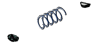
The shape is automatically generated and the length of the
branch is displayed in the Length box.
- Optional: To modify the
external curve:
- Right-click the External Curve box and select Reset.
- Select another external curve in the geometry.
Or,
- Directly edit the external curve.
- Click OK when done.
- Add other branches to join the branch you have just defined
to connectors.
- Click Classic Branch Definition
 . . - Click Route Definition and select
objects of interest to define the route of the branch.
- Click OK to validate.
- Repeat these steps for the other end.
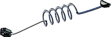
The final result looks like this:

|