Generate 2D Details for Electrical Devices, Equipment and Supports
You can use the GVS to customize the drawing of flattened data with 2D
details for devices, equipment and supports.
By default, 2D detail generation is
based on device, equipment, or support part number. A device contains an external reference attribute:
- If it is not valuated, the part number of the device is used for the 2D detail.
- If it is valuated, a 2D detail with the same name is searched in the catalog or library
mentioned in the GVS and is instantiated in the drawing.
Supports and equipment do not have any external reference attribute. You can create
an External Reference Knowledge parameter to use the same 2D
detail for several references of support or equipment:
- If the parameter is not valuated, or does not exist, the part number of the
support or equipment is chosen by default and you need to create as many 2D
details as the number of support or equipment references.
- If the parameter is valuated, the 2D detail with a name corresponding to
the parameter's value, external reference, is used.
To create an External Reference parameter for a support,
follow the steps below:
-
Select a support.
-
From the Compass, click Engineering Rules Capture.
-
Click Parameter Set
 from
the Engineer Rules Capture section. from
the Engineer Rules Capture section.
The Knowledge Engineering Specification
Physical dialog box appears.
-
Enter a representation name (Support) and click OK.
A Support node appears in the tree, with a
Parameters sub-component:
-
Select Parameters in the tree and click Parameters
Explorer
 in the Engineer Rules Capture section.
-
In the New Parameter of Type list, select the
String type, then in the opposite field
(With), select Single
Value.
-
Click New Parameter of Type and give a
Local Name: External reference.
-
In the Parameter > Value, enter:
2DDetailName.
-
Click OK.
The external reference parameter with the 2D detail name is visible
in the tree.
Generate 2D Details for Protective Coverings and its Ends
You can use the GVS to customize the drawing of flattened data with 2D
details for the protection covering and its ends. By default,
- 2D detail generation for ends is based on the external reference attribute
- 2D detail generation for protective covering is based on the exact name of the
reference part.
-
To generate the 2D details for protection covering ends:
-
Under the electrical GVS parameters, select
Yes from the
Generation list, available in and then specify the catalog name for 2D details
instantiation.
Note:
You can set generation preferences for all the available
protection types.
-
Specify external reference attribute string (same as the name of
the one specified in the catalog) that needs to be instantiated.
The 2D details at the ends of the protective covering are
instantiated in the generated 2D data. Note:
The same 2D detail is
used for both ends of the protective covering. Thus, when
defining the detail, the administrator must respect the detail
symmetry about the x-axis.
The center of the detail is placed on the end point of the
protective covering and the OX axis of the detail follows the
tangency of the curve at the previous point. When generating the
drawing, 2D details are scaled according to the layer of
protective covering to which they are applied.
-
To generate the 2D details for protection covering, set the GVS attribute
to Yes from the Generation
list, available in .
Note:
You can set generation preferences for all the available protection
types.
The element from the catalog/library named identical to the reference part name is
instantiated.
Generate 2D Details at Harness Junctions
You can use the GVS to customize the drawing with symbols representing
the harness junctions.
-
In your GVS, select .
-
Set the GVS parameters:
-
Under the Generation node, select
Yes to activate the customization
functionality.
-
Under the CatalogName node, enter the name
of a catalog/library and chapter/class.
-
Under the SymbolName node, enter the name of
the symbol to represent the junctions.
Note:
When the catalog name or symbol name is not found, the customization
is not applied even if the Generation is set to
Yes.
For more information, see Electrical
Manufacturing Preparation Parameters.
-
Click OK to validate.
When using the Front View

command, the selected symbol is displayed at every harness junction. 
Notes:
- For broken junctions due to loops, the symbol is displayed at
one of the broken extremities.
- If the harness is modified leading to junctions creation or
modification, use the Update
 command to refresh the drawing.
Generate 2D Details for Support Section Views
You can use the GVS to customize the drawing of flattened data with 2D
details for support section views. By default, one 2D detail per support section is
generated. Details are positioned on the drawing on a grid. The details of support
sections are oriented according to the orientation of the support in the 3D view.
-
Select .
-
In the Standard Definition dialog box, expand the
EquipmentAndSystems node.
-
Select Support > Representation > SectionOfSupport >
Generation node and, in the
Generation list, select
Yes to generate 2D details for support section
views.
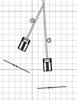
Node supports are identified by a letter and corresponding details
are identified using the same identifier plus a prefix, if desired.  In this example, the arrow on the right side is a 2D detail which is
superposed on the 3D projection of the support. The symbols used in the
drawing view can be:
- Images from the catalog if you filled the External
Reference attribute in your support with a knowledge
parameter
- A symbol named after the support part number
The automatic generation leads to the creation of following elements:
For more information, see About Customizing a Drawing View.
Generate 2D Details for Cutting Information
You can add a cutting line associated with a scissor symbol to your drawing.
These features set in the GVS show where to cut a conductor on the formboard.
The cutting line is defined by a symbol and an offset value separating the device
extremity from the cutting line.
Before you begin: In Data Setup, assign your cutting line symbol in the
Drawing catalogs or the Drawing
libraries resource.
-
In your GVS, select .
-
Set the parameters:
-
Under Generation, select
Yes.
-
Under CatalogName, enter the name of the
catalog or library in which the symbol is set.
-
Under SymbolName, enter the name of the
symbol representing the cutting line.
Note:
When the catalog name or symbol name is not found, the customization
is not applied even if the Generation is set to
Yes.
For more information, see Electrical
Manufacturing Preparation Parameters.
-
To define the offset value of the cutting line, do either of the following:
-
Generate the drawing either using the Documentation
command or the Front View command.
After the generation, the selected symbol is displayed at the extremity of every
device assembly.
Note:
The cutting line must be drawn perpendicular to the axis of the
branch connected to the device assembly and align with the origin of the y-axis.
|
