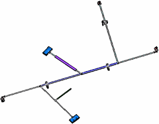
Generate the Front View
You can generate and update text templates, annotations, and support sections on electrical components in the Drafting app.
-
Open the flattened document.

-
Open a new drawing document.
The Drafting app opens.
-
From the
View Layout section of the action bar, click Front View
 and
select the top-face of the rectangular connector as Plane.
The drawing document updates according to this choice:

Text Templates are generated on:
- Segments
- Protective coverings
- Connectors (single insert connectors, ground studs, internal splices, external splices, terminal strips and terminal blocks)
- Backshells.
Notes:- You can customize the text templates of the information
tables and assign the same to the required SIC devices. To
do so:
- Right-click the required SIC device node in the tree, select Properties, and then click the Electrical tab.
- In the External Reference
box, enter the name of the device symbol and the
text template, as declared in the drawing catalog
using Data Setup, separated by a semicolon.
For more information about Data Setup and the text template catalog, see Administration: About Data Setup for Electrical Manufacturing Preparation and Managing Text and Table Templates.
When the device symbol name (or the text template name) is not specified in the External Reference box, the default device symbol (or the text template) appears in the connector information table.
- Create a new drawing of this flattened data.
The connector information tables are displayed based on the text templates specified for SIC devices.
- To generate text templates on equipment and systems, click Me > Preferences > Standards to customize Equipment And Systems parameters in the Standard Definition dialog box. After selecting the generativeparameters category, you can select the XML file to customize.
- For a text template and a conductor annotation table to be created for a splice having no draw items projected in the drawing, at least a point should be defined on the splice. This point is projected in the drawing and used to attach the text template and conductor annotation table.
The connector tables automatically positioned beside its related device are generated on:
- Segments
- Connectors (single insert connectors, ground studs, internal splices, external splices, terminal strips and terminal blocks).
The Support Sections are generated on:
- A ditto for each support section
- Appropriate labels on the support itself and on the section for easy identification.
As specified in the generative view style, the rectangular connectors are replaced with the chosen 2D detail and the protective coverings and segments are displayed with a double line.
With the generative view style, you obtain:
- The segment with a single line or a double line
- The protective covering with following elements:
- A single line (with line type definition) or a double line
- A 2D detail at extremity (with level coverage management)
- A color filling corresponding to the color of the protection
in the 3D designNote: Color filling is only available for protections generated in double line mode. Moreover, a protection present at a rolled portion cannot be filled.
- Supports and devices with a 3D projection or 2D detail (stored in the PLM Setup).
The integration behavior is the same for:
- View from 3D: A view from 3D that is extracted from a 3D shape representation.
- Advance front View
For more information about Front View, View from 3D and Advance front View, see Drafting User's Guide.
Note: You can generate text templates containing attributes defined from different packages for a single component.