- Open a product containing at least one support with several branches.
- Flatten the 3D harness content.
-
Select the electrical geometry in the flattened view.
- Open a new drawing document.
In the Drafting app, an empty sheet is
created. -
From the
View Layout
section of the
action bar, click Front View.
The Generative view style dialog box appears
and the Generative view style option is selected by default. - From the flattened view, select a plane in the electrical geometry.
-
Click anywhere in the drawing.
The drawing view of the geometry, with the support, is generated in the sheet.
-
From the
Electrical Dress-up
section of the
action bar, click Segment Arrangement View
 and select the support in the drawing. and select the support in the drawing.
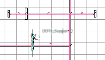
When you hover the pointer over a support, the name of the support appears.  Note:
The following symbol  can also appear to indicate that a support is not selectable. can also appear to indicate that a support is not selectable.
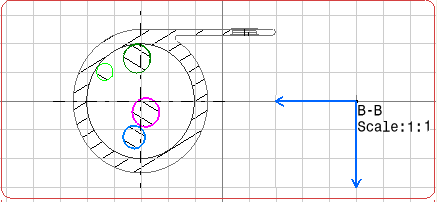
- Click the sheet to select the position of the segment arrangement view.
The drawing displays the view of the segments' arrangement in the support.

Notes:
- The segment arrangement view is based on the drafting clipping box capability. The exact frame of the support is displayed. You can also select the projection of a 2D detail.
- The axis system of the section view is the same as the constraint vector of the support. Therefore, the orientation of the view is compatible with the torsion analysis. For more information, see Vectors.
- The viewing direction depends on fork conditions. For more information, see About Segment Arrangement View.
- Before generating text templates on the view, you need to edit the GVS. To do so:
- In the Standard Definition dialog box, expand the DefaultGenerativeStyle node and select node.
- In the TextTemplateName box, enter the required title.
For more information, see Customizing the Drawing.
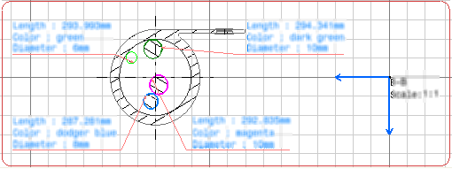
- To instantiate text templates on the segment arrangement view, double-click the segment view (B-B) to activate it
and click Front View
 from the
View Layout
section of the
action bar. from the
View Layout
section of the
action bar. text templates are generated on the segments:  Notes:
- A text template is generated on every support present in the drawing. It can be executed on all support section views. Moreover, the section view is generated for all the sections defined in the support and no separate section view is generated per support section.
- Multi-profile segments (circular or rectangular) can be considered in the support section view.
- Open the Electrical 3D Design app
- From the Branch section of the action bar, select the Arrange Segments
 and then select a support. and then select a support.For more information, see Electrical 3D Design user's guide: Arranging Segments in Supports. - In the work area, move the segments to the desired location
inside the support.
- Click OK.
- Update both the 3D product and its 2D representation.
The drawing view of segment arrangement is updated. 
|