Arranging Branches in an Equal Angle Pattern | ||||
|
| |||
- From the Formboard section of the action bar, click Prepare Layout
 .
. -
On the context toolbar, click Arrange Junction
 and then Equal
  .
.

-
Select the branch around which other branches required to be arranged near
the junction.
This branch is referred to as the fixed branch. The equal angle pattern is applied on all segments from the far segment end. A rule defines the fixed segment between following:
- Segment with the biggest diameters
- Segment with the longest length of branch if diameters are same
- Random selection if lengths are same
There are two ways of selecting the angle of rotation:
- If the Branch Point of a branch is selected as the rotate pivot point, the branch splits at this point and the split segments is put in a new branch.
- If the branch end is selected as the rotate pivot point, no split is done and the whole branch is rotated.
To see a message during the branch split when you rotate the segments, select an option in Me
 > Preferences > App Preferences > 3D Modeling
> Equipment > Electrical Discipline > Electrical Harness Flattening > General expander.
For more information, see
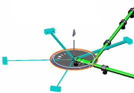
General.Note: The minimum angle allowed between the branches while rotating the branch is zero deg.A preview highlights the junction and shows how branches are arranged.
- Click the work area background to validate this first action.
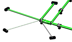
A clash appears with another segment. To avoid this clash, rotate the whole structure.
-
Select Global Mode
 to work on the four branches at once and apply rotation on the whole.
- Rotate the four branches.

-
Click the work area background to accept the arrangement.
