Using the GVS to customize the Drawing with Text Templates

You can create text templates on the drawing of flattened harness thanks to the Front View command. Before this, you need customize dress-up capabilities in the generative view styles (GVS). Text templates are generic types of texts which are intended to be instantiated in various drawings or layouts.

You can learn how to edit, store and instantiate text templates on CATIA products or sheetmetal instances in the Drafting User's Guide: Working with Text Templates. You can use the same commands to create text templates manually and instantiate them on the drawing of an electrical component or attributes.

Note: You can store the text template in an existing catalog or library, and you can store this catalog or library in Data Setup.

For more information, see Administration: About Data Setup for Electrical Manufacturing Preparation


Before you begin:
  • Clear the Disable generative view style usage check box under Generative view style, available in Me > Preferences > App Preferences > 3D Modeling > Mechanical > Drafting > Administration tab.
  • Set up your environment to use the GVS. For example, create GVS_sample_1.xml.
  • The GVS parameters can be set in Me > Preferences > Standards for the Drafting app.
  • Click Me > Preferences > Standards and, in the Standard Definition dialog box, follow the below steps:
    1. In the Category list, select generativeparameters.
    2. In the File list, select GVS_sample_1.xml file.
    3. Click Drafting > Generate > 3DPoints and in the Wireframe list, select Yes to generate test templates.
  • Open the Drafting app.
  1. From the Annotation section of the action bar, click Text with Leader to create a text reference in the detail sheet in a drawing that contain the reference texts.
    1. Select the text.
      The Insert Link Template window opens, in which you can choose the component's attributes to add in the text template when you select the appropriate Package and component type.
    2. To define electrical components (a device for example) in text templates, select the Electrical Physical Package.
    3. To define PLM components in text templates, select the PLMCoreModel Package.
    4. To define electrical attributes, select the Single Insert Connector Extension type
    5. To define PLM attributes in text templates, use the PLMCoreReference type.
      The attributes of a type are listed in the Text Editor dialog box.
    6. Click OK.


  2. Store the defined text template in a catalog or library.
  3. Set the catalog or library in the specific Data Setup resources table.
    The catalog or library is used to retrieve the text template reference.
  4. Specify the following GVS parameters under Electrical > Device, from Me > Preferences > Standards:
    • TextTemplate > Generation: Set to Yes.
    • TextTemplate > CatalogName: To search for it in the Data Setup.
    • TextTemplate > TextTemplateName
  5. From the View Layout section of the action bar, click Front View and select the top-face of the device as Plane.
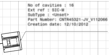
    The drawing document displays the multiple-attribute text template on the device:
    Note: If you modify the original 3D document for example to change a segment diameter, change a connector or device position or add or remove a branch etc., you need to update the drawing. For more information, see update