-
From the Dimension section of the action bar,
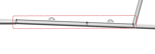
click Multiple Dimensions
 .
.
The Electrical Dimensions dialog box appears.
-
Hover the pointer over the different segments.
The available measure points appear.

By default, the available measure points for supports or protections are the entry and exit points. Ctrl
+ hover over the support or protection to show the middle measure point.
To make this a default option, select the Measure
Point is always the middle of support and protection check box under
Electrical Dimension, available in
expander.
-
Click the required measure points.

 : Indicates selected measure points.
-
In the Electrical Dimensions dialog box, click
OK.

To reposition the dimensions, you can click the annotation and move them up, down,
right, or left.
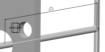
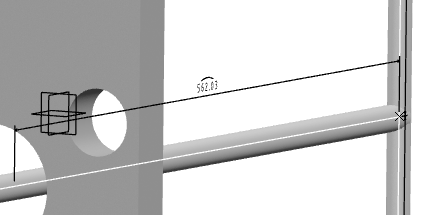
You can specify the offset distance between the dimension
line and the dimensioning element in the Offset distance box,
available under Dimension offset in
section. For more information, see General.
| Dimension with Default Offset Distance (20mm) |
Dimension with 10mm Offset Distance |

|

|
Note:
In the tree, the dimensions are created inside the representation, under the Electrical
Dimension Set and the Annotation Set.X nodes. The
feature called Electrical Dimension stores the specifications of the
dimension: the two ends and the path (i.e. list of segments).


