Customize Preferences
You can manage tangency using options available in the
Preferences dialog box.
In
, select the Formboard tab and
customize the following preferences:
-
Under Component orientation, select
Closest preferred plane.
-
Under Tangency and shape at device junction,
select the Keep branch definition check box.
-
Under Offset from global xy plane, enter a
distance in mm.
For more information about these options, see Formboard.
Customize Business Logics
You can implement business rules to customize the generation of your layout.
Generate the Formboard Layout
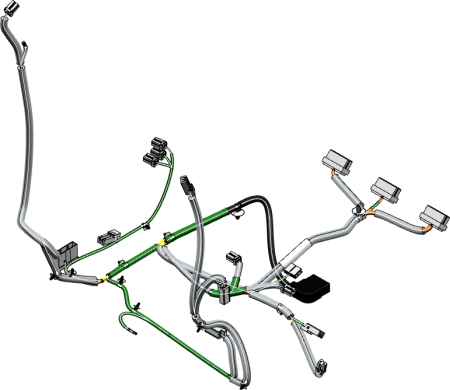
You can generate the formboard layout of the 3D harness in one single
process.
-
Open the harness data in an authoring tab.
-
From the Formboard section of the action bar, click Formboard
 . .
The command is not available if a generated layout is already open.
-
Select one of the following:
- An electrical physical system
- Required electrical branch geometries
Notes:
- You can click Select all to select all
the electrical geometries.
- If you select another electrical physical system after previous
selection, previous selection is not considered.
- In the 3D area, the selected content is
highlighted.
- In the Formboard Process panel, under the
Selection
tab, the selected elements are
listed. You can click
 to filter the selection. to filter the selection.
- The Validation button is available.
-
Click Validation to check the network connectivity.
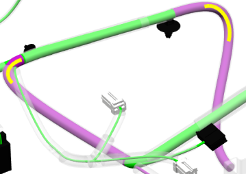
The content (branches, supports, devices, and mechanical parts) is
highlighted as below:

|
The content is validated. |

|
The content is not validated
because of discrepancy. |
If discrepancies are found, the Validation button
is displayed with icon  and the expanders between following are displayed in the
Validation
tab:
 You can click Validation to validate the
connectivity. The Validation button is displayed
with  icon.
-
Click Backbone and then select the required start
and the end elements of the harness backbone.
Note:
You cannot select a 3D part with junction point as a start or end
device for the backbone.
- The labels, START and
END, appear on a selected branch. The
branch with
 color indicates the backbone. color indicates the backbone.
- The Backbone button is displayed with
 icon. icon.
- All the branches forming the backbone are listed in the
Backbone
tab under
Report. The flatten status and the total
rounded-off length of backbone branches is displayed.
The Harness Identification button is
displayed with  icon. -
Click Layout Options to confirm the orientation
vector of start device of the backbone and to choose how to flatten the
branches.
By default, all the branches have flatten status as
Flatten. You can click the branch successively
till the required flatten status appears. For more information, about the
various flatten status, see Preparing the Flattening Process.
- The new flatten status of the branch appear in the
Flatten status
tab under
Report.
- In the Comment column, the next flatten
status that you can specify is displayed.
- Optional:
Apply filters to the required columns to display the required values.
-
Click Generate layout to start the formboard
generation process.
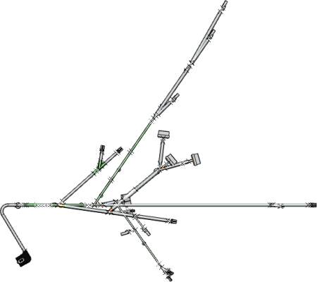
The formboard layout appears in a new tab.
- The backbone is aligned with the x-axis from left to right with
start device placed on left-hand side.
- The flattened layout is generated by maintaining the tangency of
backbone branches orienting the secondary branches on relevant side
of the backbone.

|


