Customize Preferences
You can manage tangency using options available in the
Preferences dialog box.
-
In
, click the Formboard
tab and customize the following
preferences:
-
Under Component orientation, select
Component torsion free.
-
Under Tangency and shape at device junction,
clear the Keep branch definition check box.
-
Under Offset from global xy plane, enter a
distance in millimeter.
- Optional:
Under Torsion management, select the
Make support not constraining check box.
-
Select the General tab, and under
Extract and Synchronize check, select the
Electrical connection check box.
For more information, see Formboard and General.
Customize Business Logics
You can implement business rules to customize the generation of your layout.
This stage is optional.
Generate the Formboard Layout
You can generate the formboard layout for the 3D harness.
-
Open a 3D design harness in an authoring tab.
-
From the Formboard section of the action bar, click Formboard
 . .
The command is not available if a generated layout is already open.
-
Select one of the following:
- An electrical physical system
- Required electrical branch geometries
Notes:
- You can click Select all to select all
the electrical geometries. You can also use button to deselect
the all the selected geometries.
- If you select another electrical physical system after previous
selection, previous selection is not considered.
- In the 3D area, the selected content is
highlighted.
- In the Formboard Process panel, under the
Selection
tab, the selected elements are
listed. You can click
 to filter the selection. to filter the selection.
- The Validation button is available.
-
Click Validation to check the network connectivity.
The content (branches, supports, devices, and mechanical parts) is
highlighted as below:

|
The content is validated. |

|
The content is not validated
because of discrepancy. |
If discrepancies are found, the Validation button
is displayed with the icon  and the expanders between following are displayed in the
Validation
tab:
and the expanders between following are displayed in the
Validation
tab:
-
Click Start element.
The devices available for selection are identified in the following
colors:
-
 : Indicates devices with a symmetry plane. : Indicates devices with a symmetry plane.
-
 : Indicates devices with no symmetry plane. : Indicates devices with no symmetry plane.
For more information about symmetry planes, see Flattening of Bend Devices.
-
In the 3D area, select a device as start element of
the layout generation.
 : Indicates
the selected device. : Indicates
the selected device.
The selected device is listed in Start element
tab under
Report.
- Optional:
Apply filters to the required columns to display the required values.
-
Click Generate layout to generate the formboard.
The formboard layout appears in a new tab.
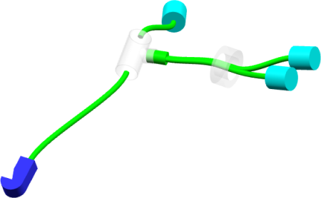
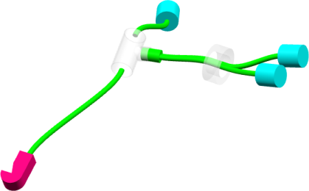
- The branch connected to the device you selected as start element is
aligned with the x-axis and tangency is kept at the branches
junctions.
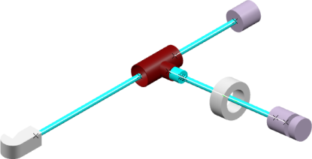
- The generated layout is torsion-free.

|
 > Preferences > App Preferences > 3D Modeling
, click the Formboard
tab and customize the following
preferences:
> Preferences > App Preferences > 3D Modeling
, click the Formboard
tab and customize the following
preferences:

 .
. 