Angle Modes
The Angle mode parameter determines the angular spacing between segments once they are flattened.
You can set this parameter in the General tab of the Harness Flattening Parameters dialog box or in the Generate Layout dialog box.
Two modes are available: Standard and Regular.
Standard
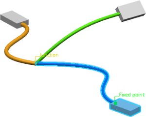
Flattening in Standard mode enables to keep in the flattened harness the same angles as in the original 3D harness. The spacing between the segments respects the minimum angle value set in the general parameters.
When working in Standard mode, the branches identified as the backbone of the harness are aligned and flattened straight on the active plane. This improves the default layout and reduces the layout manipulations after the flattening process.
By default, this mode is selected.
| Extracted Content | Flattened Content |
|---|---|
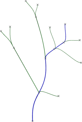 |
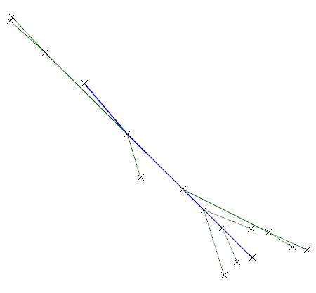 |
Backbone Identification
The identification of the harness backbone is based on the starting branch and on a weight calculation conducted on the rest of the network.
The starting branch is the first branch which belongs to the backbone. It is determined as follows:
- If you select a branch and then click Select All Branches in the Generate Layout dialog box, the selected branch is the starting branch.
- If you select a device and then click Select All
Branches in the Generate Layout
dialog box, the branch connected to the selected device is the
starting branch.Note: If you select a device assembly or a device connected to several branch, the first identified branch during the navigation is the starting branch.
- If you select an electrical geometry, an electrical branch geometry, or an electrical physical system, the longest branch in the network is the starting branch.
Then, at each junction of the starting branch, a weight calculation enables to determine the next backbone branch. This calculation is based on the length of the branches and the number of devices which are connected to the starting branch.
After the calculation, the branch with the highest weight is added to the backbone.
- If the highest weight is found on several branches, the branch which has the highest diameter is added to the backbone.
- If the highest diameter is found on several branches, the branch which has the highest length is added to the backbone.
The calculation process is repeated until the last junction in the network is reached.
Regular
Flattening in Regular mode enables to evenly space the angles between segments by calculating regular angles.
This mode is recommended to create the topology of a harness because the orientation and the angles of the segments are not kept.
| Extracted Content | Flattened Content |
|---|---|
 |
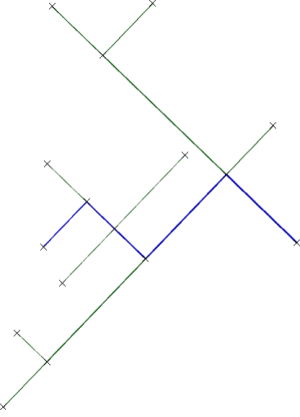 |
Regular Angles Calculation
Regular angles are calculated in predefined target directions depending upon the number of segments and branches.
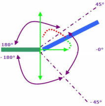
It is possible to use Flatten Harness branch orientation at junction to better match 3D harness design branch orientation at junction. As an example, let us consider the case of a model consisting of two or three branches.
 |
45º > angle < -45º |  |
| 180º > angle > 45º |  |
|
| 180º > angle > -45º |  |
The computation of angle between two branches is done between the branch end and the first point of intersection.
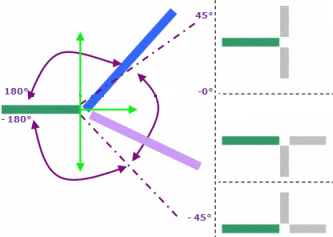
 : Blue or
purple branch
The angle computation between two branches is only applied in Regular mode. The branch direction is calculated with the exact tangency at the branch end (between the branch extremity and the first passing point).
If the directions of all the branches are in same junction are different, this computed direction is used to fit it as possible as with the Regular angle mode.
If there are at least two segments with the same direction, the algorithm is not launched.
