About the Flattening Results | ||||||
|
| |||||
- Segments on External Curves
When flattening segments on external curve, the external curve is migrated to a standard electrical curve. Both the length and bend radius (equal to the diameter) of the external curve are kept.
- Branch Routed Through a Curve
When flattening a branch routed through a curve, the curve is included into the extracted content. Hence the shape of the harness is the same after the extract process.
When the branch is flattened, the curves used as routing elements are merged into the branch route. The curve is not part of the route after flattening. The branch length and all the flattening commands (like Roll, Rotate,etc.) are not impacted by this capability.
You can also synchronize the changes done in harness content (containing the branch route with a curve) into flattened content. The curve's location is not impacting because the curve is not part of the route after the branch is flattened.
- Mechanical Parts
When flattening a geometry containing mechanical parts, a dashed green line visualizes the link between the segment and the mechanical part. Use the Robot to reposition the part properly.
- Segments Routed through the Same Support
- When flattening several segments routed through the same support, only one segment is kept. The links of other segments are broken and a green line is created.
- Geometries Containing Closed Loops
- Electrical geometries containing closed loops are detected and can be flattened.
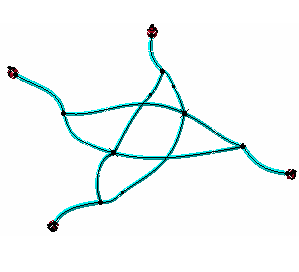
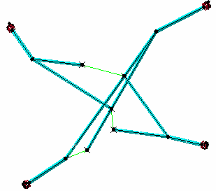
Closed loops are managed at branch level and not at segment level. When flattening geometries containing closed loops, the system breaks:
- The mechanical link at a system-defined point. A green line is created between both ends of the previously joined branches. This green line is created between two points: the point that existed before the loop was opened and a new point created at one of the branch ends. The green line informs where the system had to open the loop.
- The electrical link.
Before Flattening After Flattening 

You must close the loop manually by rotating, rolling, etc. the branch.
Important: - To break a loop at a user-defined point, straighten one of the branches by selecting correctly select fixed and free ends of the branch.
- When a protective covering is placed over more than one branch in a loop, it is recommended that you break the loop at a user-defined point by straightening a branch over which there is no protective covering.
- Rigid Branches
- If you decide to modify the flatten status of the branches before flattening them, the rigid flattened status enables a rigid branch to be flattened but not straightened to keep some bend portions.
As a consequence, bend portions are automatically rolled if they meet the following criteria:
- Bend radius value is less than the maximum bend radius. By default, the maximum bend radius is five times the bend radius of the branch.
- Bend angle value is more than the minimum bend angle. By default, the minimum bend angle is 45 degs.
These values can be customized using a business rule. For more information, see Flatten Rigid Branch Business Rule (EHFFlatten_ComputationRigidBranchFlatten).
Tip: The Porcupine Curvature Analysis command enables you to check for bend portions in the 3D area. For more information, see Generative Shape Design User's Guide: Analyzing Curves and Surfaces: Analyzing Using Porcupine Curvature. Important: By default, the first identified bend portion of a branch is rolled in a positive direction. The roll direction of the next bend portion is calculated by comparing its bend with the bend of the previous portion. - If both bends are in the same direction, previous roll direction is applied to the next bend.
- If the bends are not in the same direction, the opposite direction of the previous roll is applied to the next bend.
- If the first identified bend does not meet the above criteria, no roll is applied to the bend. In this case:
- If the next bend has the same direction as the first identified bend, then positive roll direction is applied to the bend.
- If the next bend is in the opposite direction of the first identified bend, then negative roll direction is applied to the bend.
- Junctions
- When you flatten a harness containing junctions, the tangency of the branches present at a junction point are taken into account.
As a consequence, the relative position of the segments is the same in the flattened content as in the extracted content. Moreover, segments which are part of the harness backbone are aligned and flattened straight.
Important: - This behavior is only available when flattening non-arranged junctions in Standard mode.
- Torsion analysis is not taken into account when you flatten junctions. During the process, junctions are not rotated. Only the organization of the segments inside a junction is kept.