-
From the
Formboard section of the
action bar,
click
Harness Flattening Parameters
 , and define the parameters as follows: , and define the parameters as follows:
-
In the
General
tab,
choose an
Active plane.
-
In the
Flattening Orientation
tab,
select
Device placed in the active plane.
For more information, see
Defining Harness Flattening Parameters.
- Click Extract
 to duplicate your 3D harness content. to duplicate your 3D harness content.For more information, see Extracting 3D Content. - Click Generate Layout
 , and then select a branch or a device in the work area. , and then select a branch or a device in the work area.
The
Generate Layout
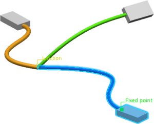
dialog box appears. In the 3D area: - The connected objects are highlighted.
- The Junction and Fixed point tags represent the starting and ending points.

- Optional:
Edit the Active plane and/or the
Angle Mode.
- To expand your partial selection, select another branch.
Note:
You can select another branch only if the
previous one is also selected.
- Click OK.
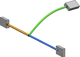
Your selection is flattened. 
|