You can compare the
relative torsion between 3D design harness and a laid out harness. The
Analyze Torsion command also provides the tools to modify and
nullify torsion.
You can visualize the relative torsion of the laid out harness.
From the Formboard section of the action bar,
click Analyze Torsion.
In the Torsion Analysis Prerequisites dialog box, the
conditions required to analyze torsion are listed.
Tip:
Select Do not show this message again to skip
this dialog box during the next analysis.
Click Continue.
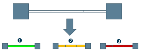
In the Torsion Analyzer panel, select the torsion statuses to be
displayed in the 3D area:
Critical
Moderate
Normal
Note:
By default, all the statuses are selected. To visualize a specific status, keep
the related check boxes selected. In the work area, the deselected elements become transparent and are not analyzed.
Select an electrical physical system, an electrical branch geometry, or a branch to
visualize its torsion.
The Torsion Analysis Report panel appears that displays
the torsion report in the form of pie chart. You can click Report
to check the torsion values and to export the
report.
The Torsion Analysis Report panel appears.
The content is colored according to the various torsion statuses.
Vectors appear and a yellow curve displays the effect of torsion
on the branches.
Vectors also appear in the 3D design harness content
tab.
3D Data
Flatten Data
Note:
The torsion for the consecutive branches
with same segment profile, segment flexibility, and dimension is analyzed together
which results in the same torsion value for them. The critical torsional value for
each torsional segment is calculated by giving the total length of all consecutive
torsional segments as an input to the business rule. Thus, the torsional analysis
shows the same result status (critical, moderate, or normal) for all these consecutive branches.Torsion Analysis with Business Rule
The torsional analysis using business rule shows the result status between
, , or
.
You are now able to manipulate objects to edit the torsion of the
harness.
Edit the Torsion
You can manipulate devices, device junctions, and supports to modify and nullify
torsion.
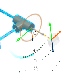
To edit the torsion of a segment by manipulating a device:
Select a device in the 3D area.
An angle manipulator displays the current angle value of the torsion
applied to the segment.
Rotate the device or edit the angle value using the angle manipulator.
In the Torsion Analysis Report panel, the relative
torsion value is updated in real time.
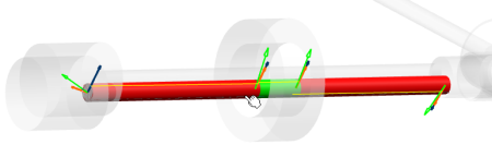
In the 3D area, the yellow curve reflects the torsion changes.
When the torsion reaches the normal status, the edited portion turns
green.
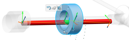
To edit the torsion of a segment by manipulating a device junction:
Click the branch near the device junction.
Select the device junction.
An angle manipulator displays the current angle value of the torsion
applied to the segment.
Rotate the junction or edit the angle value using the angle manipulator.
In the Torsion Analysis Report panel, the relative
torsion value is updated in real time.
In the 3D area, the yellow curve reflects the torsion changes.
When the torsion reaches the normal status, the edited portion turns
green.
To edit the torsion of a segment by manipulating a support:
Select a branch with a support.
Select the segment portion to edit near the support.
Important:
When the Make support not constraining
check box is selected, Ctrl + select the segment portion
near the support.
The support is highlighted. An angle manipulator displays the current angle value
of the torsion applied to the segment.
Rotate the support or edit the angle value using the angle manipulator.
In the Torsion Analysis Report panel, the relative
torsion value is updated in real time.
In the 3D area, the yellow curve displays the torsion changes.
When the torsion reaches the normal status, the edited portion
turns green.
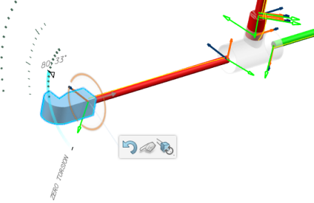
Select the ZERO TORSION tag to rotate the selected element and
reach a torsion-free segment in one step.
Click in the 3D area to
validate the modifications and double-click to exit the command.
 .
.
 to export the
report.
to export the
report. 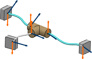

 ,
,  , or
, or
 .
.